Bittle
Table of Contents
- 1. Learning Outcome
- 2. Workspace Setup
- 3. Hardware Setup
- 4. Bittle Body
- 5. Electrical and Controller Properties
- 6. Calibration
- 7. Controlling Bittle
- 8. Extensible Modules
- 9. Serial Commands Cheat Sheet
- 10. Tasks
-
11. Teach Bittle New Skills
- 11.1. Understand skills in InstinctBittle.h.
- 11.2. Example InstinctBittle.h
- 11.3. Define new skills and behaviors
- 11.4. Understand OpenCat.h
-
11.5. Tutorial on Creating New Skills
- 11.5.1. Preparation
- 11.5.2. Understand the format of a posture
- 11.5.3. Explain expected body orientations
- 11.5.4. Explain angle ratio
- 11.5.5. Understand the format of a gait
- 11.5.6. Understand the format of a behavior
- 11.5.7. Understand the memory structure
- 11.5.8. Create a new behavior
- 11.5.9. Tune skills in realtime
- 12 Advanced Tasks and Troubleshooting
1. Learning Outcome
1.1. Introduction


1.2. Requirements
- Arduino Basics
- Visual Studio Code Basics
- Introduction to Version Control with Git
1.3. What you need
1.3.1. Hardware
- Bittle robot
- Arduino UNO
- Electronics Kit (including sensors)
1.3.2. Software
- Visual Studio Code
- Git Version Control
- Arduino IDE 1.8.X
- Node-RED
1.4. Sources and Resources
- VS Code
- GitLab
- GitLab Extension for VS Code
- PlatformIO
- Arduino IDE
- Git
- Professional Git by Brent Laster (available online in University Library)
- Petoi Bittle User Manuals
- Bittle Online Help
- Node-RED
- Git Book V2
- Real-time C++ Fourth edition. ISBN 3-662-62996-8 (University Library)
2. Workspace Setup
In this section, all the required software is installed. Visual Studio Code is used for the code development.
Todo
Please download the presented software with the links provided in their respective sub-sections.
2.1. Visual Studio Code
Visual Studio Code is a source code editor. It supports various programming languages and can be combined with compilers to work as a package integrated development environment IDE.
VS Code has IntelliSense which allows word-based completions. This helps you write code syntax without typos.
You also get access to various extensions. These enhance the working of VS Code and also add new features as per requirements.
Todo
- Download and install Visual Studio Code.
2.2. Arduino IDE Extension
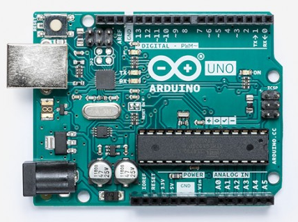
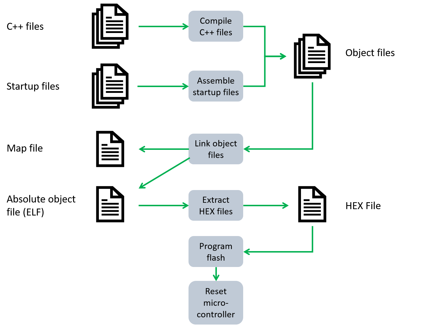
The introductory programming sessions will be conducted using the Arduino UNO board. The board can be programmed using C++. To write the code, the Arduino extension will be required in Visual Studio Code. This code will then be compiled using a GCC compiler and uploaded to the board using a flashing program. For uploading, the board has to be connected to the PC using a USB A (PC side) to USB B (UNO side) cable.
Todo
- Download and install the Arduino IDE to program your Arduino Uno. Version: 1.8.X
- Check if VS Code automatically detected the installed Arduino IDE. If not, follow these steps:
- Open Extensions from Activity Bar. Search for the Arduino extension.
- Click on the small gear icon (manage menu) next to it. It will open a new menu.
- Click on Extension Settings. A new tab will open.
- Scroll down and find Arduino Path.
- Enter the complete installation address of your Arduino IDE, e.g.,
C:\Program Files...
More information about the extension can be found in the Visual Studio Code Basics.
Todo
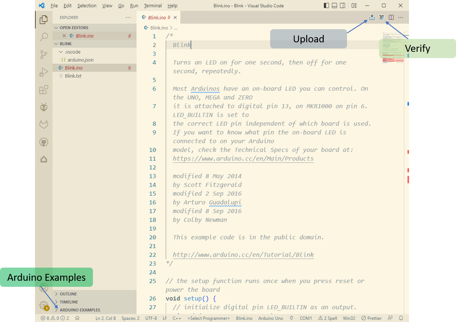
- Check out the Arduino examples provided with the libraries on the Side Bar. Open and test the Blink example.
Open Explorer and at the end, a section named Arduino Examples can be expanded. Expand Built-in Examples -> 01. Basics -> Blink. A new window with the example will open.
Todo
- If you have not yet worked with the Arduino IDE before, follow this course on Arduino Basics.
2.3. Version Control using Git and GitLab
A version control system allows you to keep track of the changes that have been made to code over time. This means that you can, at any given point in time, revert to older versions of the code you are working on.
Git is a popular version control software. Git works on Distributed Version Control Systems. This system provides everyone with a copy of all files and allows users to edit them locally. The user can then work on the files locally and upload the files to the server. The advantage of DVCS is that if a server crashes, a local user can upload the files and make it running as they have a complete copy of the server data.
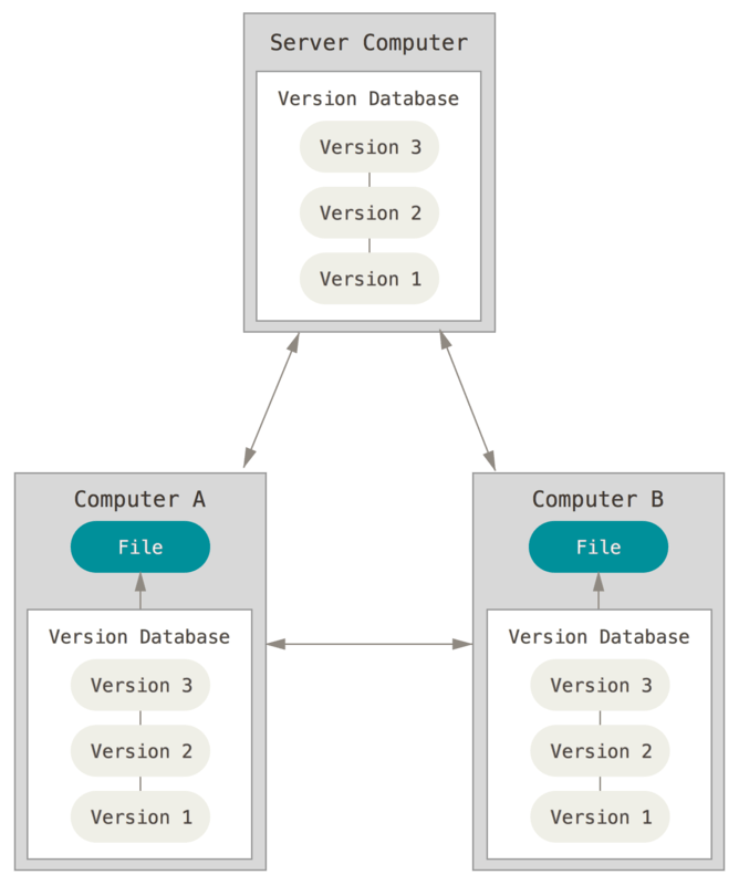
In this course, Git will be used as part of Visual Studio Code.
Todo
- Download and install Git on your device.
- If you have not yet worked with Git before, please follow this course on Introduction to Version Control with Git.
GitLab is a DevOps tool used for hosting Git repositories. It allows collaborative teamwork to develop software. The difference between Git and GitLab or other platforms (Bitbucket, GitHub) is that these platforms allow users to upload their Git projects online. This makes collaborative teamwork easy. As for Git, you can even work with Git on a local computer without the need for a hosting platform. The local Git project will stay for your use only and would not be shared directly with your teammates.
We will be using GitLab for this course as our university hosts a server, thus making it easy for us to use the platform. To use the University’s GitLab server, use the following link: FH Aachen GitLab.
You can check access by logging onto the website using your FH-Kennung (FH identifier) (e.g., AB1234S) and password.
Todo
- Create a profile for the FH Aachen GitLab account and confirm that you have access to the GitLab server of your university.
- Add your GitLab account to Visual Studio Code. You can follow the steps outlined in Visual Studio Code Basics.
- Create a new repository for your project. Share the repository with your teammates with proper access rights.
- Create a new branch apart from the Main (Master) branch. Work in the new branch only. When you are sure about your work, merge the changes from the new branch to the Main (Master) branch.
2.4. Node-RED
Node-RED is a programming tool for wiring together hardware devices, APIs, and online services in new and interesting ways. It provides a browser-based editor that makes it easy to wire together flows using the wide range of nodes in the palette that can be deployed to its runtime in a single click. (ref: Node-RED)
Todo
- Download Node-RED for your device and follow the Quick Start introduction.
The Palettes menu on the left side contains all the available nodes that can be used for designing a flow. The nodes are sorted by their use, and the tree structure can be expanded and collapsed as per requirements.
External libraries can be installed on Node-RED using Palette Manager. You can open Palette Manager from the top right menu in Node-RED.
Todo
- If you have not yet worked with Node-RED before, follow this course on Node-RED Basics.
- Please install the following palettes:
2.5. Everything ready?
Todo
Check if you have the following setup running on your PC:
- Visual Studio Code ready.
- Arduino IDE 1.8.X ready.
- Arduino Extension can be used in VS Code.
- Your GitLab account is accessible via VS Code.
- You have a repository created on the GitLab website and it’s cloned on your PC using VS Code.
- Node-RED is running on your device and you can access it via your web browser.
3. Hardware Setup
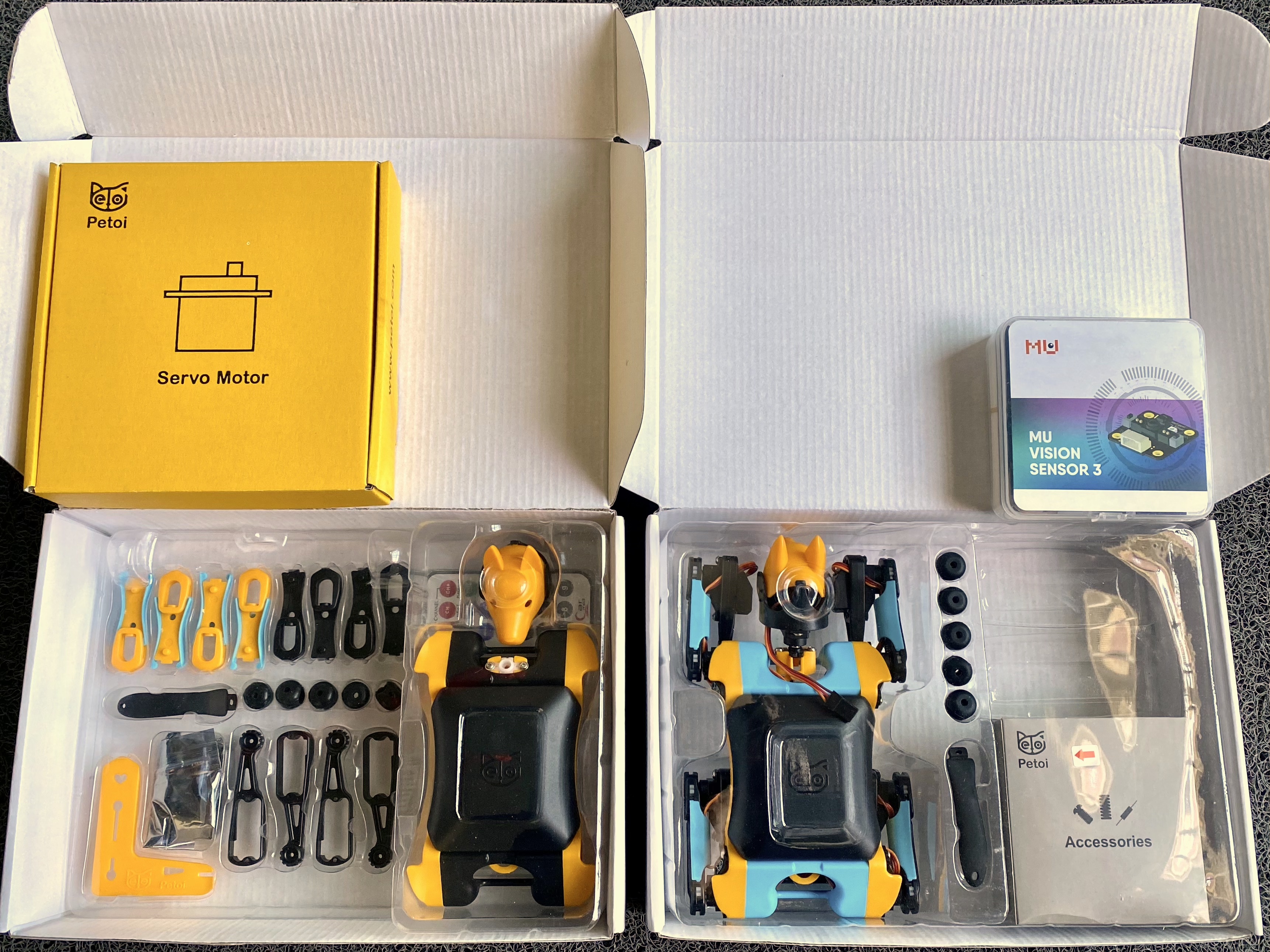
3.1. Pre-assembled kit
Todo
If you received the pre-assembled Bittle, you need to:
- Insert the neck into the body.
- Bend the knees to natural angles.
- Drag the curly wire from the knee side to the shoulder side to avoid squeezing when the knee joints rotate.
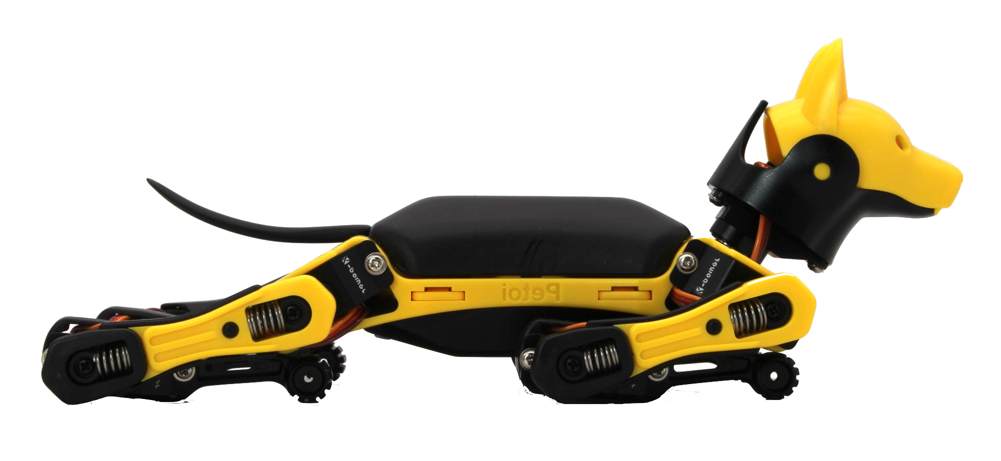
- Put the joints into the following posture before turning on the power.
- Long press the battery’s button for 2~3 seconds to power on/off.
Warning
The pre-assembled Bittle is only coarse-tuned. You still need to calibrate Bittle’s joint servos and final assembly to fine-tune its joints for the best performance.
- If a small calibration is required, it can be done using App/Code. This will be done in the upcoming sections.
- If the deviation is more than that possible with App/Code, you need to remove the corresponding part of the servo and re-install. Please refer thisfor details.
3.2. Base kit
Todo
If you received the base kit with the single parts, you need to follow the tutorials provided:
4. Bittle Body
The walk pattern of animals is nicely explained and presented here.
Various other parts can be found here.
The robot is built using custom body parts. PLEASE be careful when removing and installing parts.
To access the main board, you need to remove the back cover of Bittle. The back cover has a Click-Lock mechanism.
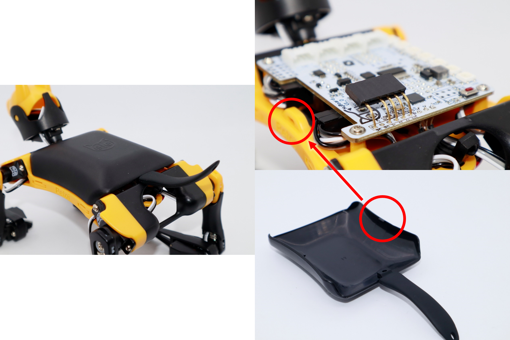
5. Electrical and Controller Properties
There are three main components in Bittle:
- the main board on top, protected by a plastic cover.
- the servos installed at each joint. (The motor shaft represents the joint. The motor body is connected with the limb.)
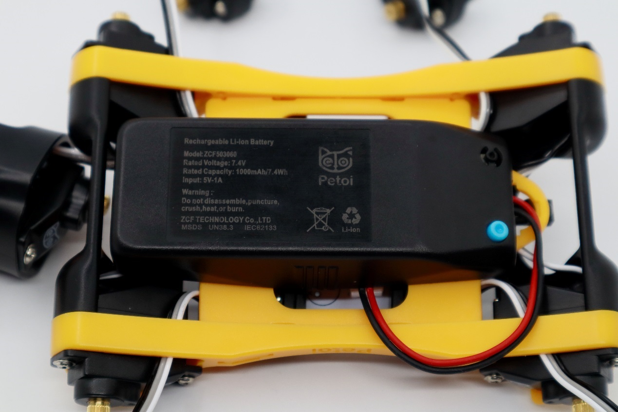
- the battery pack installed at the bottom.
Todo:
- Familiarize yourself with the hardware provided.
5.1. Main Board
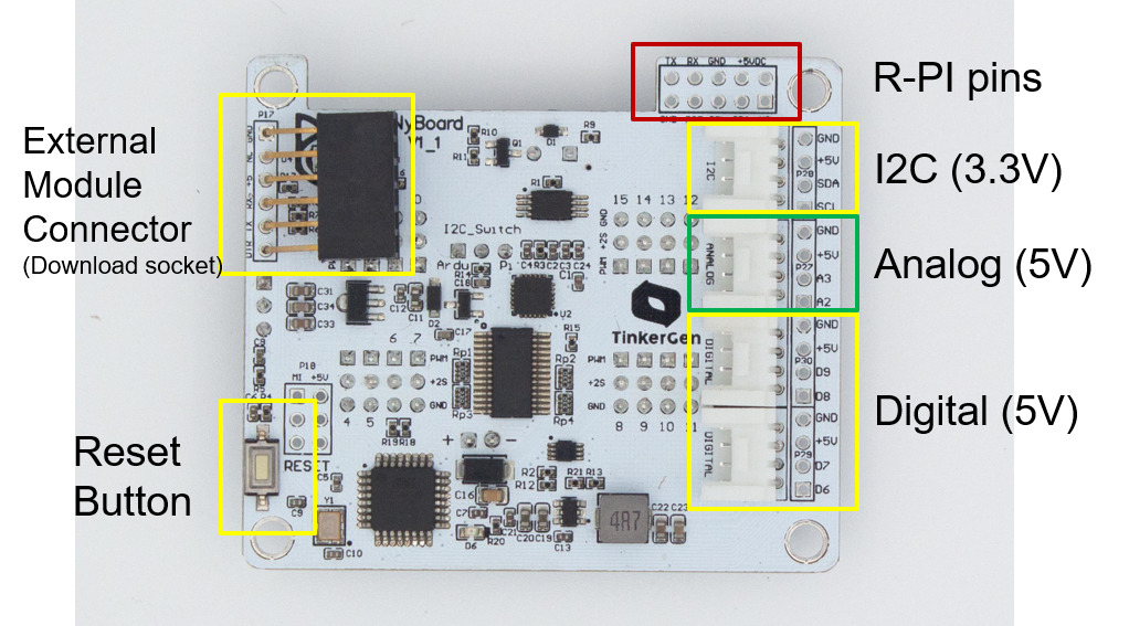
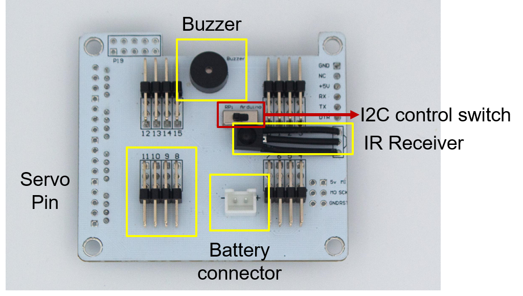
5.1.1. Specifications
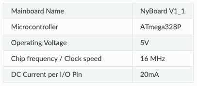
Controller Specifications:
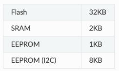
Memory Usage:
External Interface:
- UART
- I2C (TWI)
- SPI
Additional On-Board Components:
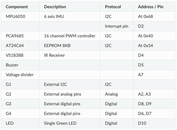
5.1.2. Board Interface
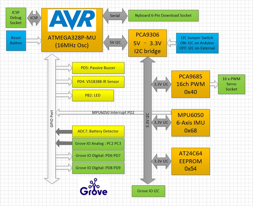
5.1.3. Board Power Supply
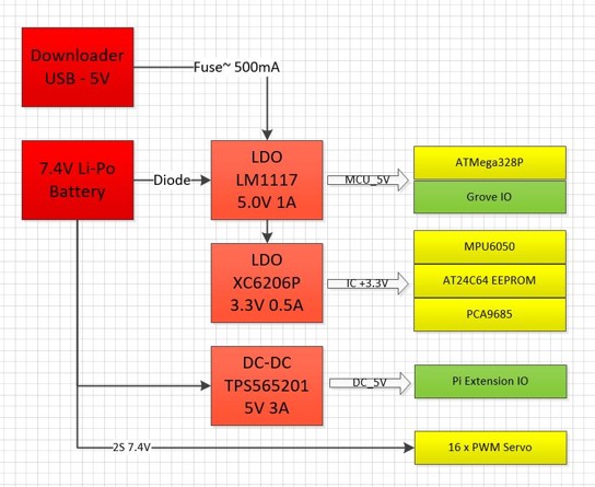
The actual voltage is about twice the ADC reading. A safe range for battery voltage is below 10V. Please recharge the battery in time when it drops below 7.4V.

The main chips are powered by low-dropout (LDO) voltage regulators:
- LM1117-5V for 5V chips
- XC6206P-3.3V for 3.3V chips (in series with the 5V LDO for better efficiency)
Other protection features:
- Diode between battery and LM1117-5V (for reverse polarity protection)
- Self-healing fuse (6V, 500mA) on the USB programming port
Raspberry Pi power supply:
- TPS565201 DC-DC converter with 5V 3A output (max 5A) with overcurrent, overvoltage, and overtemperature protection
Servos:
- Powered directly by 2S Li-ion batteries.
- Be careful not to short any pin on the NyBoard.
5.2. Servos
The servos carry out the robot’s movements. They can be set to specific angles by PWM signals.
Each servo includes:
- a DC motor
- a gear system
- a potentiometer to measure angle
Wiring:
- VCC
- GND
- PWM input
PWM Control:
- For example: 1 ms = -90°, 2 ms = +90°, 1.5 ms = 0°
5.3. Battery
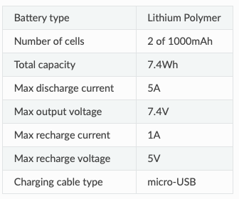
Specifications:
5.3.1. Battery Status
LED during operation or idle:

Charging status:

6. Calibration
Calibration is done to remove misalignment of servo motors. If not done properly, the robot will have issues in walking due to imbalance and jerky movements.
To calibrate Bittle, there are five methods:
- Use Mobile App (First choice)
- Use Desktop App
- Use Serial Monitor inside Arduino IDE / PlatformIO
- Long-press the battery and boot up the robot with one side up. It will enter the calibration state automatically.
- Press 📐 (calibrate) button on IR remote.
The following steps in image are same for all methods.
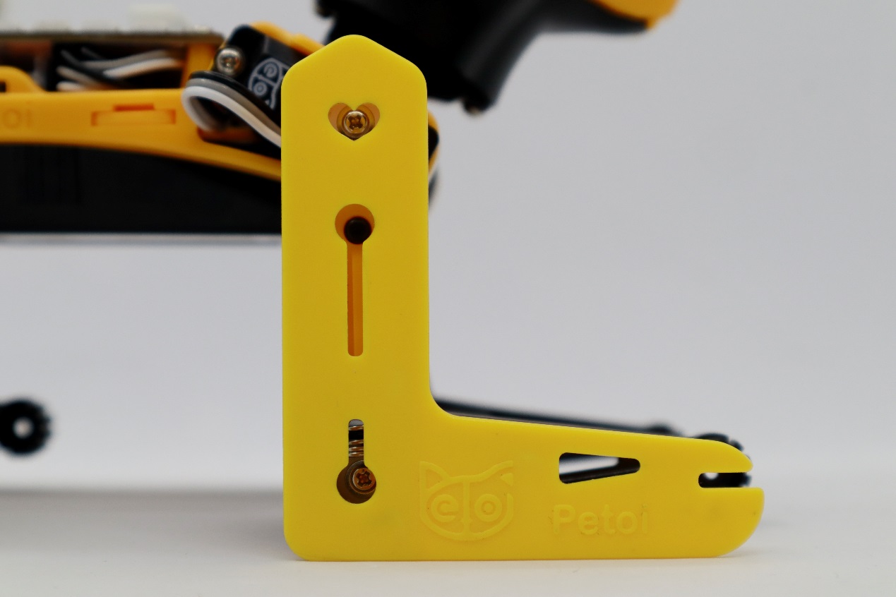
Calibration Tool (L tool)
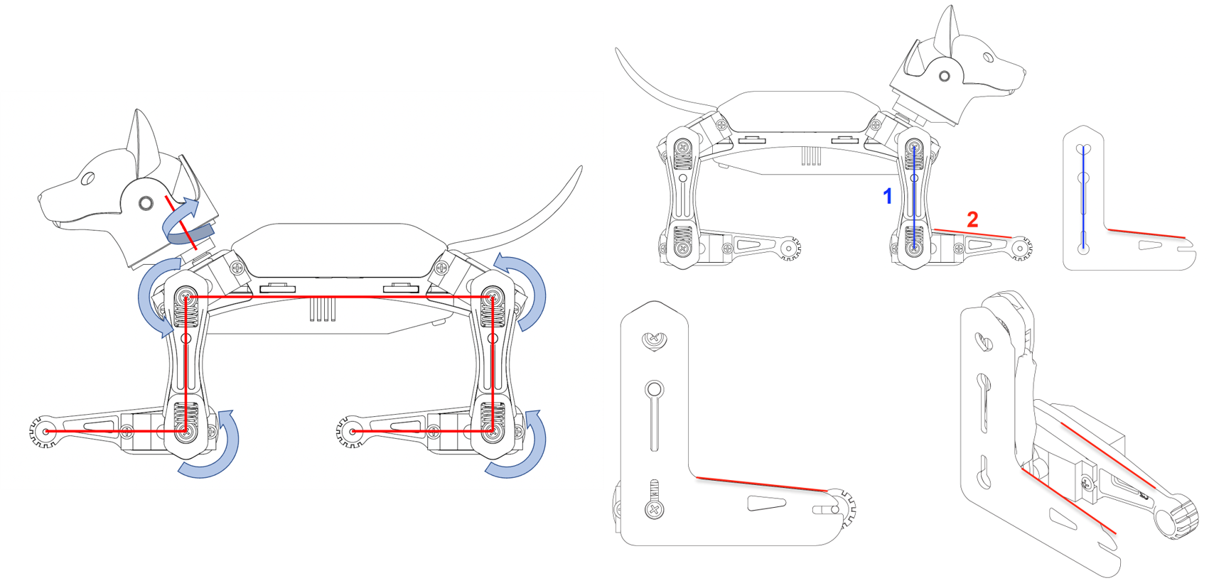
It’s especially important that you keep a parallel perspective when calibrating Bittle. Use the ‘L’-shaped joint tuner as a parallel reference to avoid reading errors.
Align the tips on the tuner with the center of the screws in the shoulder and knee joints, and the little hole on the tip of the foot. Look along the co-axis of the centers.
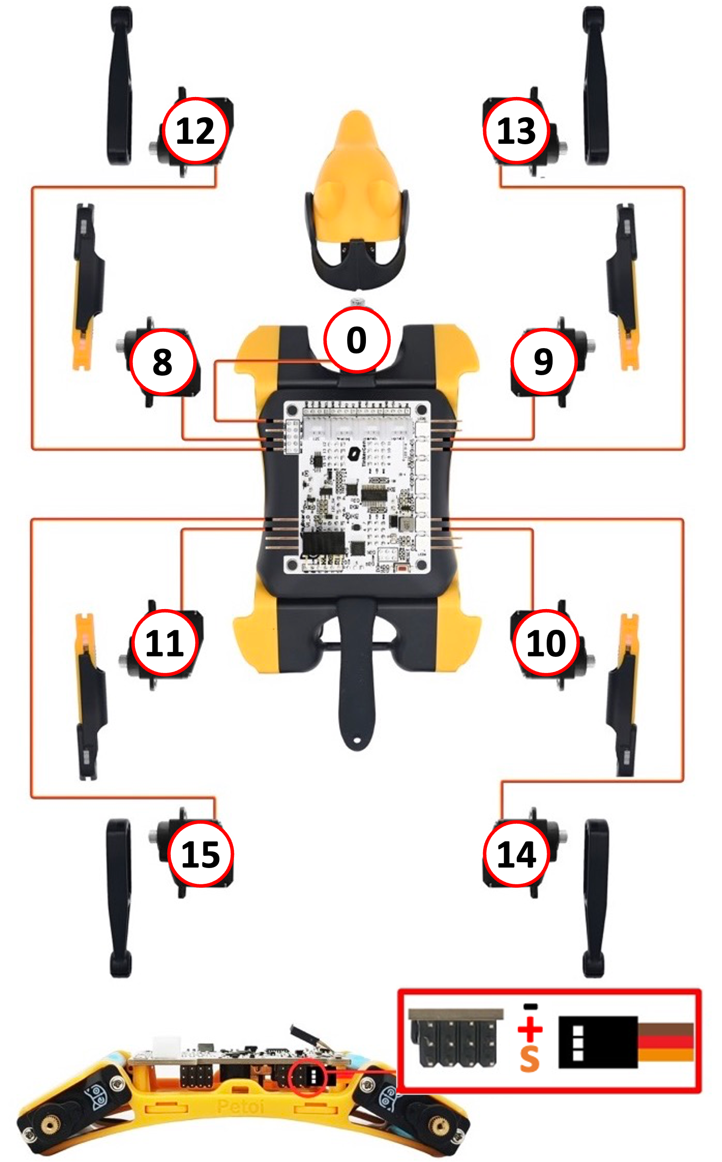
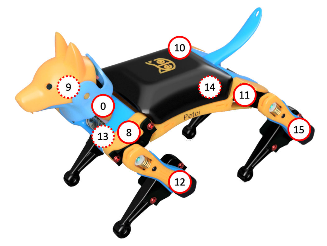
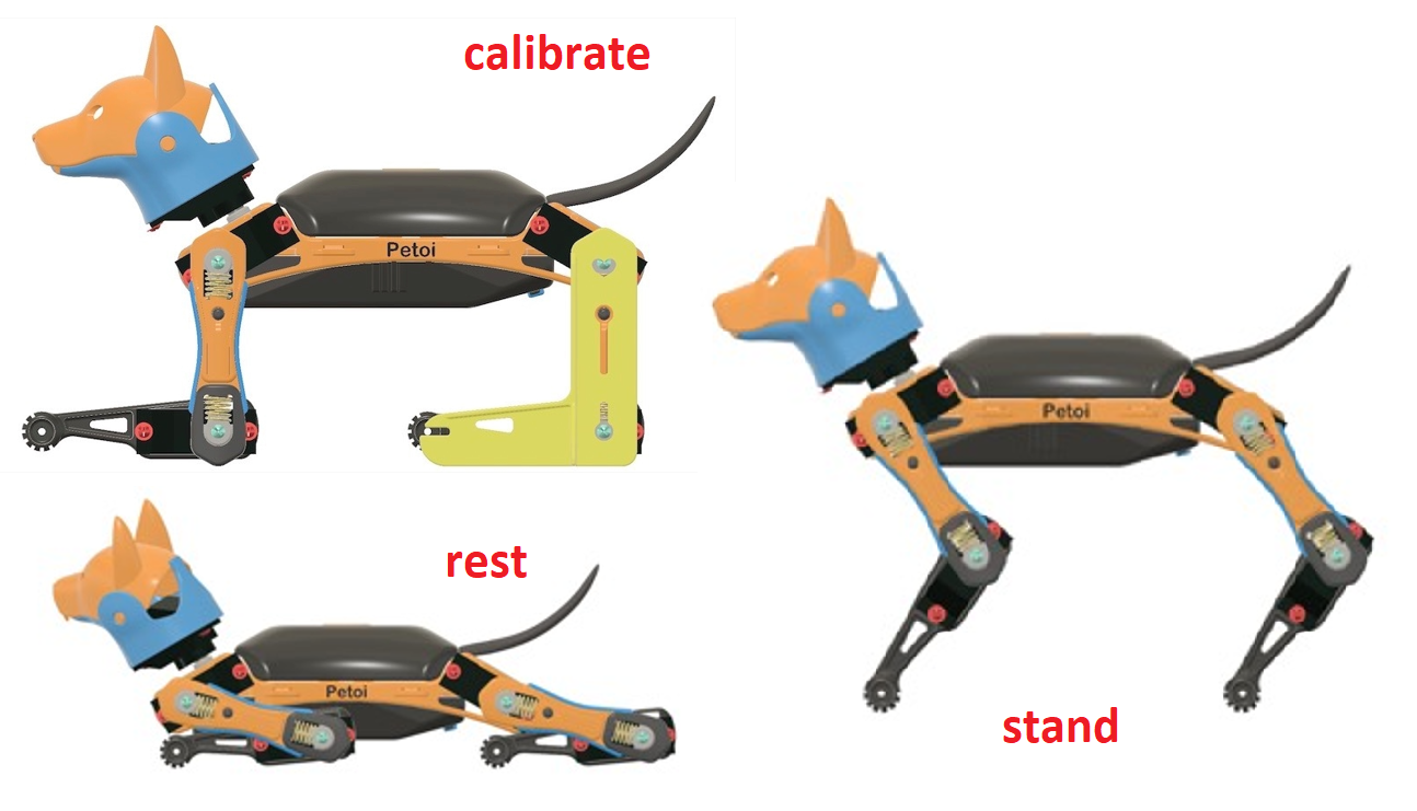
For each leg, calibrate the shoulder servos (index 8–11) first, then the knee servos (index 12–15). When calibrating the knee, use the matching triangle windows on both the tuner and shank to ensure parallel alignment.
Servo Gear
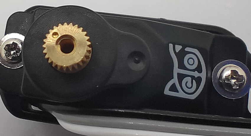
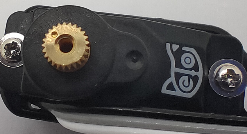
The servo gear in the image below divides 360 degrees into 25 sectors (1 gear tooth = 1 section), each taking 14.4 degrees (offset of -7.2 ~ 7.2 degrees).
Center of Mass
Try to understand how the robot keeps balance even during walking. If you are adding new components to the robot, try your best to distribute its weight symmetrically about the spine. You may also need to slide the battery holder back and forth to find the best spot for balancing. Because the battery is heavier in the front, you can also insert it in a reversed direction to shift the center of mass more towards the back.
⚠️ Danger
Before calibrating, PLEASE check the following:
- All connections are tight and no loose wires are hanging from the robot.
- Battery is completely charged
- Additional adaptor used is connected properly and the pins are in exact order.
Please do not force the robot to add heavy objects, which may cause the servos to sweep or get stuck.
If something is not working, please check Problem Solving section.
6.1. Using Mobile App
To use Mobile App for calibration, you need to install Bluetooth Adaptor to Bittle.
Pay close attention to the Bluetooth Adaptor’s pin order in the image below.
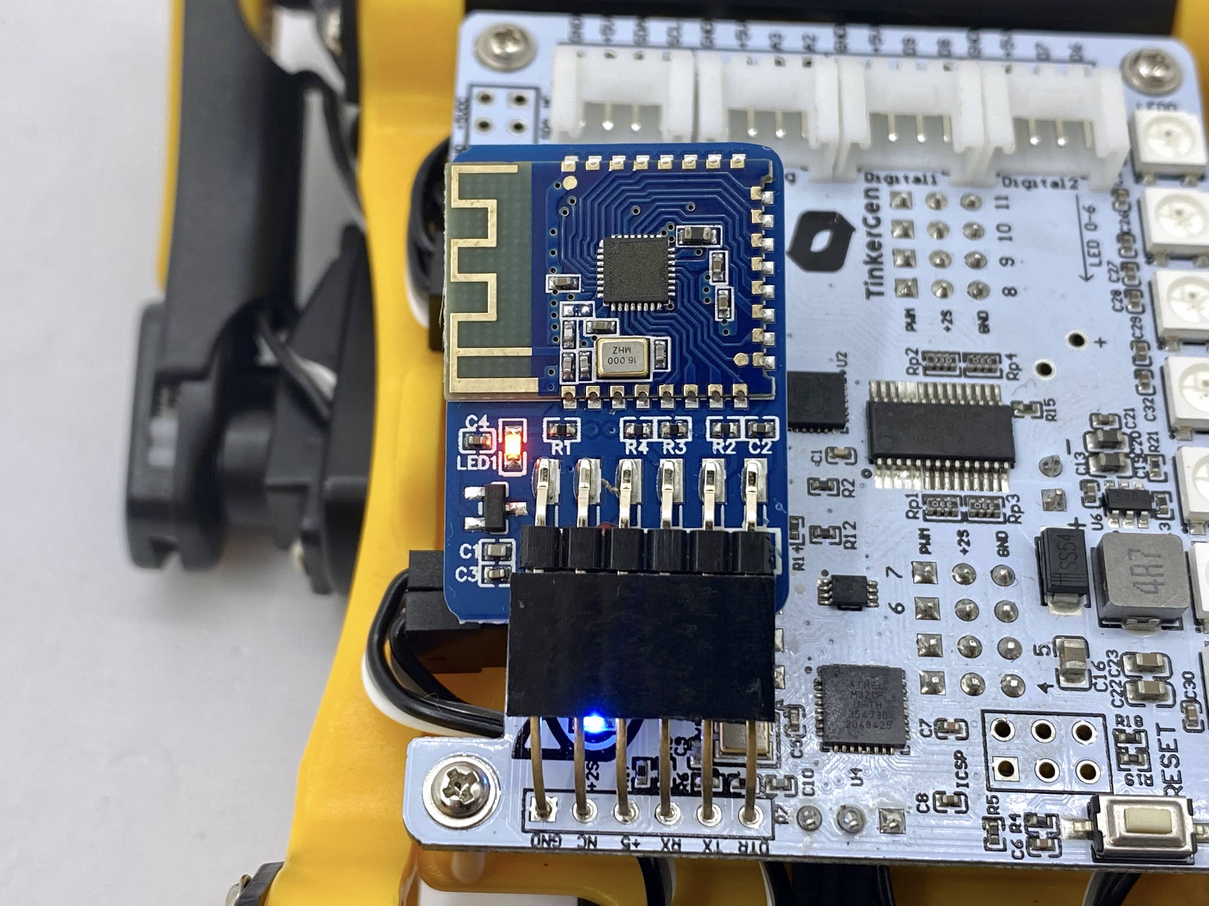
After connecting the adaptor and powering the Bittle, the LED on the adaptor should blink to indicate that it’s waiting for connection. To pair it with app follow the steps below:
- Download the mobile app:
Android
iOS: https://apps.apple.com/us/app/petoi/id1581548095 - Open the app and scan available bluetooth devices inside the app. (DO NOT connect Bittle from Phone’s system settings.)
- Grant permissions to the App to use Bluetooth services.
- Bittle may show with the following names in the App: Bittle, Petoi, or OpenCat.
- Select Bittle in Robot Selection (if asked by the app).
- Once done, you will be redirected to control dashboard.
Calibrate Bittle:
- Tap the triple dot menu from TOP RIGHT corner.
- Select Calibrate. Follow the on-screen instructions to fine-tune your robot.
- After calibration, remember to tap the Save button to save the calibration offset. Otherwise, tap
<(back) in the TOP LEFT corner to cancel and revert changes.
If the offset is more than +/- 9 degrees, you need to remove the corresponding part of the servo and re-install. Please refer this for details.
6.2. Using Desktop App
To use Desktop App for calibration, you need to install USB Adaptor to Bittle.
Pay close attention to the USB Adaptor’s pin order in the image below.
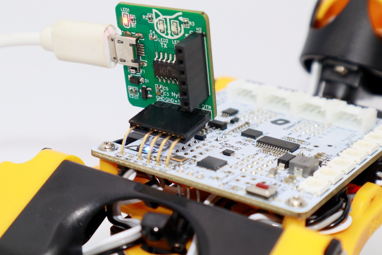
After connecting the adaptor and powering the Bittle, follow the steps below:
- Download the desktop app (Windows & Mac)
- Open the app and select the robot model as Bittle.
- Select the interface language (if asked).
- Click on Joint Calibrator.
- Click on Calibration/Calibrate to set all servos in calibration position.
- Use the slider to adjust the servo angles using the L tool.
- You can change posture (stand/rest) to validate alignment.
- Click Save to store the calibration offset. Otherwise, click Abort to cancel.
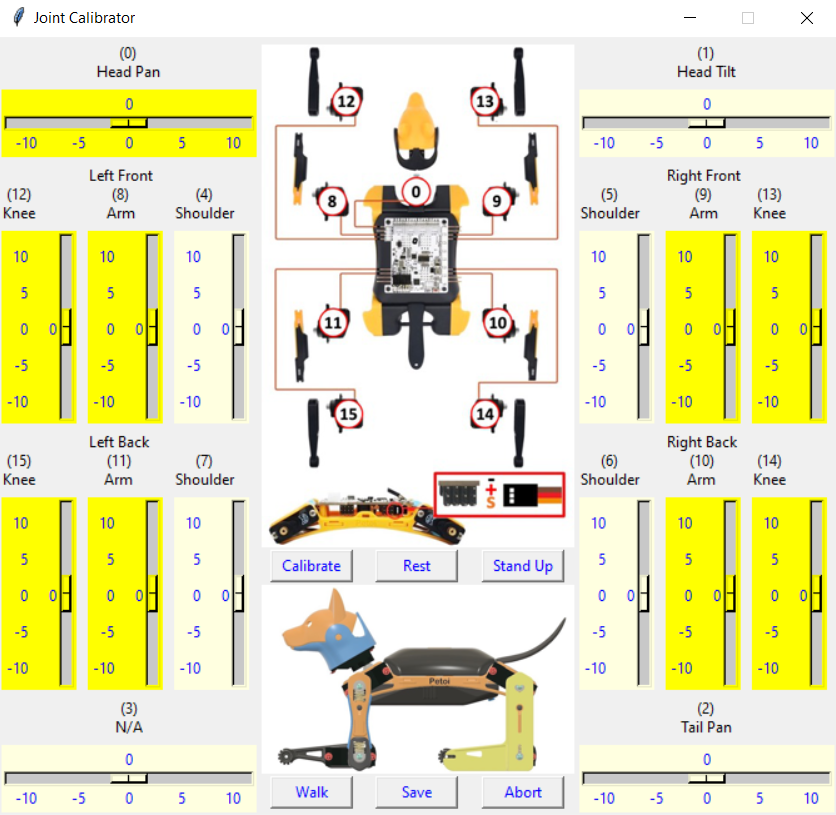
If the offset is more than +/- 9 degrees, you need to remove the corresponding part of the servo and re-install. Please refer this for details.
6.3. Using Serial Monitor
To use Serial Monitor for calibration, you need to install USB Adaptor to Bittle.
Pay close attention to the USB Adaptor’s pin order in the image below.

Follow these steps:
- Download the Arduino IDE or PlatformIO
- Open the IDE, select the COM Port and open Serial Monitor
- Set baud rate to
115200, line ending to No line ending - Type
cand press enter to enter calibration mode - You’ll see 2 rows of numbers:
- First row = motor index
- Second row = current offset value
- To set a custom value:
c<servo index> <offset value>
Example:c8 6sets offset of 6° to servo 8 - Use the L tool to align physically
- Type
sto save calibration - Wait for
Readymessage - Type
dorkbalanceto validate calibration
The resolution is 1 degree. Do NOT use decimal values.

If the offset is more than +/- 9 degrees, you need to remove the corresponding part of the servo and re-install. Please refer this for details.
7. Controlling Bittle
To control Bittle, there are five methods:
- Use IR Remote (First choice)
- Use Mobile App
- Use Arduino IDE / PlatformIO
- Use Desktop App
- Use Python Scripts
To ZOOM the image, right-click the image and select "Open in New Tab".
7.1. Using IR Remote
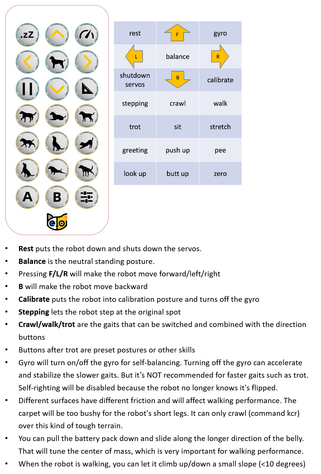
The IR command map is defined inside OpenCat/src/infrared.h.
In the file, the commands are described as #define KXX command.
For example:
K00for the 1st row and 1st columnK32for the 4th row and 3rd column
7.2. Using Mobile App
The mobile app has the following dashboard:
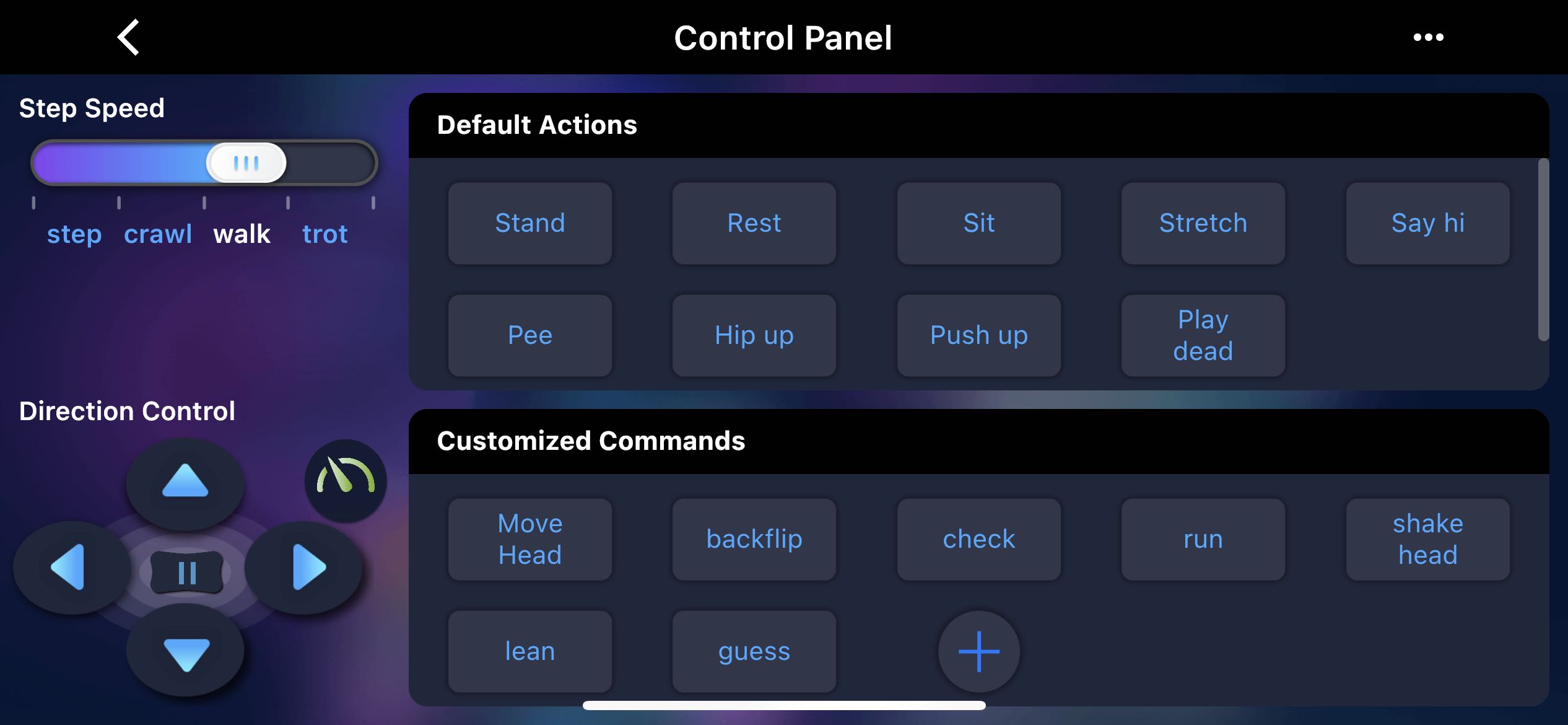
Gaits
The left panel sets the robot’s gait and direction, sending a combined command like “walk left” or “trot forward”.
The robot only moves if both gait and direction are selected.
- “Step” has no direction
- “Backward” has left/right direction options
The Pause button (||) pauses movement and turns off servos, allowing joint movement by hand.
The Turbo button (green dial icon) enables/disables the gyro:
- On = body orientation balancing
- Off = faster and more stable walking (no orientation correction)
Default Actions
Trigger built-in postures and behaviors by pressing buttons.
Do not press buttons too frequently. Allow time for Bittle to finish its tasks.
Customized Commands
Tap + to define a custom command.
Long-press a custom command to edit it.
Use the lite serial console to test/configure commands.
Example:
i 8 -30 12 40 0 35
→ Motors 8, 12, and 0 move to angles -30°, 40°, and 35° respectively.
7.3. Using IDE (Arduino / PlatformIO)
Control Bittle via serial communication using ASCII-encoded commands.
Commands are case-sensitive.
Example commands:
ksit
m0 30
m5 -15
kbalance
The complete command list is provided in the cheat sheet section.
Some commands, like the c and m commands, can be combined.
For example:
Successivem8 40,m8 -35,m 0 50can be written as:
m8 40 8 -35 0 50You can combine up to four commands of the same type.
The total string length must be less than 30 characters. You can change the limit in the code, but there may be constraints due to the serial buffer.
7.4. Using Desktop App
The desktop app has the following dashboard:
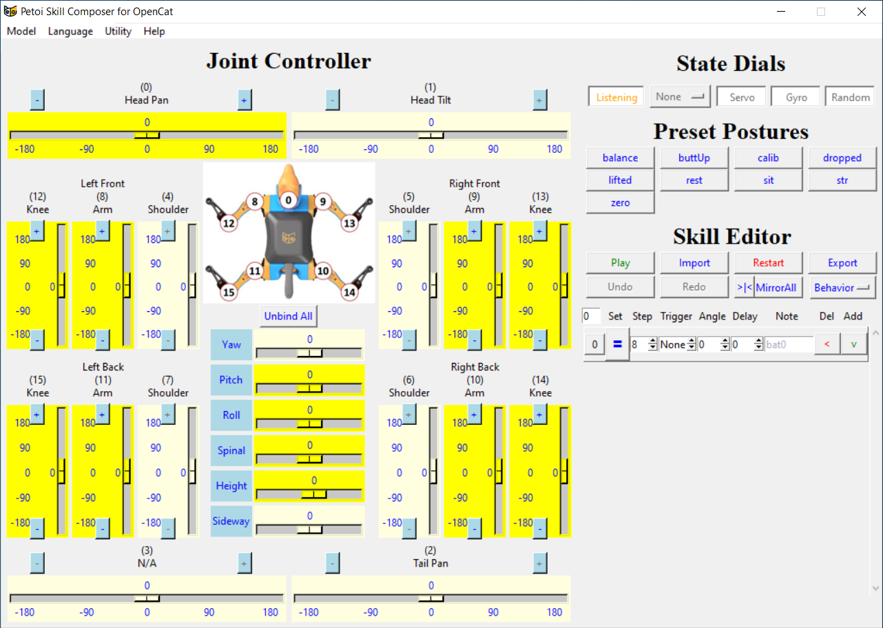
Joint Controller
- The center shows a schematic with servo indices.
- Sliders control the rotation angle in real time.
- The range is usually -180 to 180, but actual limits may vary.
- Drag sliders with the mouse to move joints in real time.
Linkage buttons:
- “+”: Forward linkage (same direction as the controlled servo).
- “–”: Reverse linkage (opposite direction).
- “Unbind All”: Cancels all linkages at once.
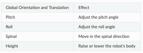
Robot Body Pose Sliders
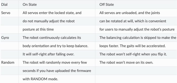
State Dials
Used to connect via USB or Bluetooth.
- Select the correct COM port (don’t leave it on “ALL”).
- Default mode is “Listening” until a device connects.
- Once connected, the status changes to “Connected”.
Buttons (after connection):
Preset Postures
Clicking these updates both the robot and UI sliders with pre-defined poses.
Skill Editor
Content under review.
7.5. Using Python Scripts
Use Python to send serial commands like predefined skills (kbalance) or custom commands (m 0 -30 0 30).
Getting Started
Open Terminal or CMD and navigate to:
OpenCat/serialMaster(See Download Base Firmware section if needed.)
Two Methods to Run Commands:
1. Using ardSerial.py
-
With parameter:
..\serialMaster>python3 ardSerial.py kbalance -
Without parameter:
..\serialMaster>python3 ardSerial.py
Type quit or q to exit the script.
2. Using Custom Scheduler
Use your own script to schedule movements with timing.
- Example:
..\serialMaster>python3 example.py
8. Extensible Modules
8.1. Sensors and Actuators
The head of Bittle is designed to be a clip to hold extensible modules. Mentioned below are some popular modules. You can also wire other add-ons thanks to the rich contents of the Arduino and Raspberry Pi community.
You can find the demo codes of these modules in our GitHub repository. The codes can be found under ModuleTests folder inside the source code.
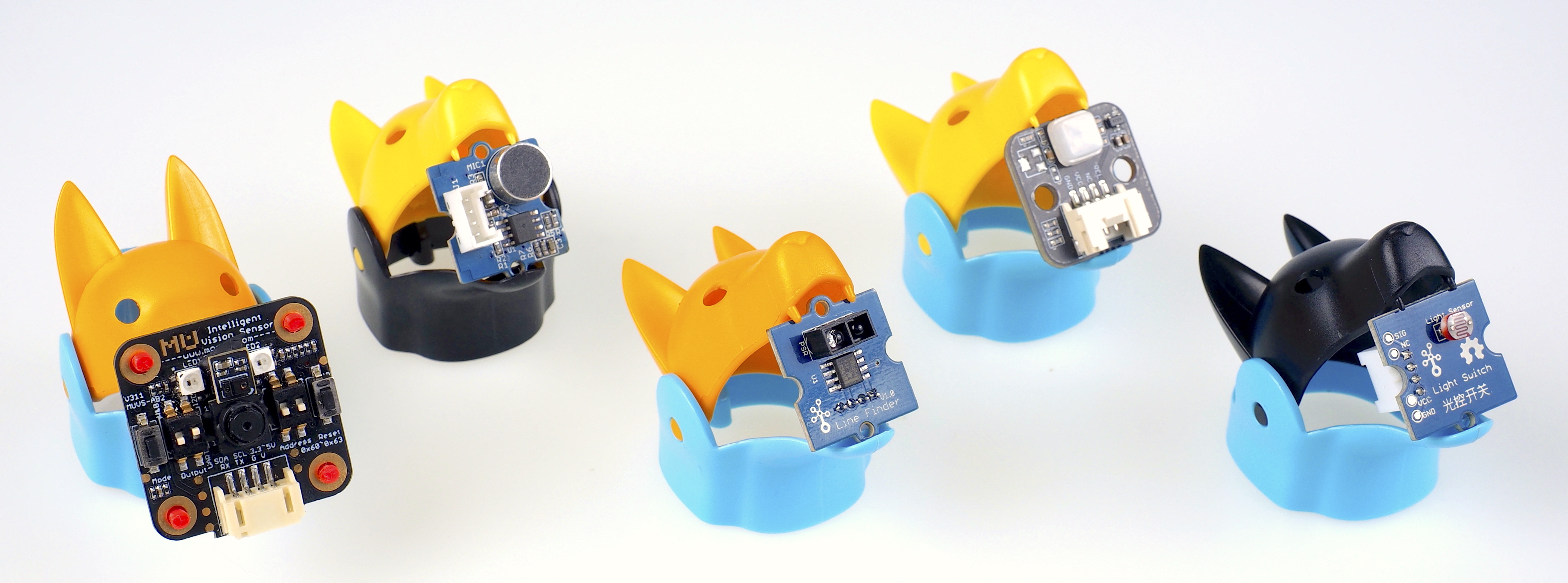
The modules are:
- LEDs
- Sound Sensor / Noise Detector
- Light Sensor / Phototransistor
- Touch Sensor
- Infrared Reflective Sensor
- PIR Sensor
- OLED Display
- Ultrasonic Sensor / Distance Sensor
8.2. Communication Modules
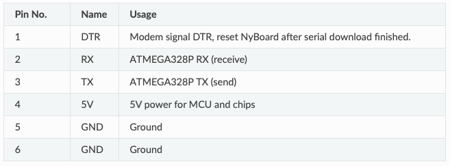
The Nyboard V1 used by robot uses the Atmel ATMEGA328P controller, which only supports only one serial port. The default serial baud rate is 115200bps. Pin definitions are shown in the table below:
8.2.1. USB Adaptor
The module uses a CH340C USB bridge. The uploader has three LEDs: power, Tx, and Rx. Right after the connection, the Tx and Rx should blink for one second indicating initial communication, then dim. Only the power indicator LED should keep lighting up.
NyBoard download interface: used to connect to NyBoard, download program firmware to the robot, and communicate with the computer via serial port.
Communication module debugging interface: used to connect the Bluetooth or WiFi module, update the module program and debug the parameters. In order to avoid the cumbersome operation when connecting with Dupont wires, the pin ordering is slightly different from the NyBoard download interface - the TX/RX interface is reversed, and a GND pin becomes an RTS pin. For details on how to use the debugging interface of the communication module, see the following chapters.
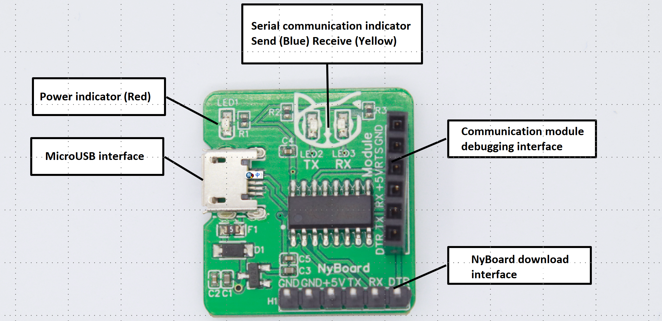

Do not plug the NyBoard and the other module(WiFi or bluetooth) at the same time!
If Tx and Rx keep lighting up, there’s something wrong with the USB communication. Please check the Adaptor and USB cable.
8.2.2. Bluetooth Adaptor
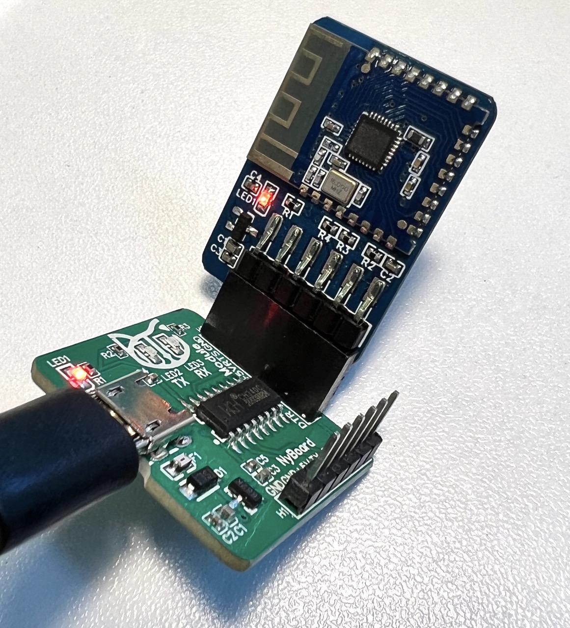
The module uses JDY-23 Bluetooth 5.0 BLE module. It acts as a bridge between Bluetooth devices and micro-controllers. You can wirelessly upload firmware or control the motion of the robot through a Bluetooth connection. This module is also required to connect with the PETOI mobile app. A blinking LED on the Bluetooth module indicates waiting for a connection. If required, the default PIN for pairing is “0000“ or “1234”. After the pairing is successful, the system will assign a serial port name.
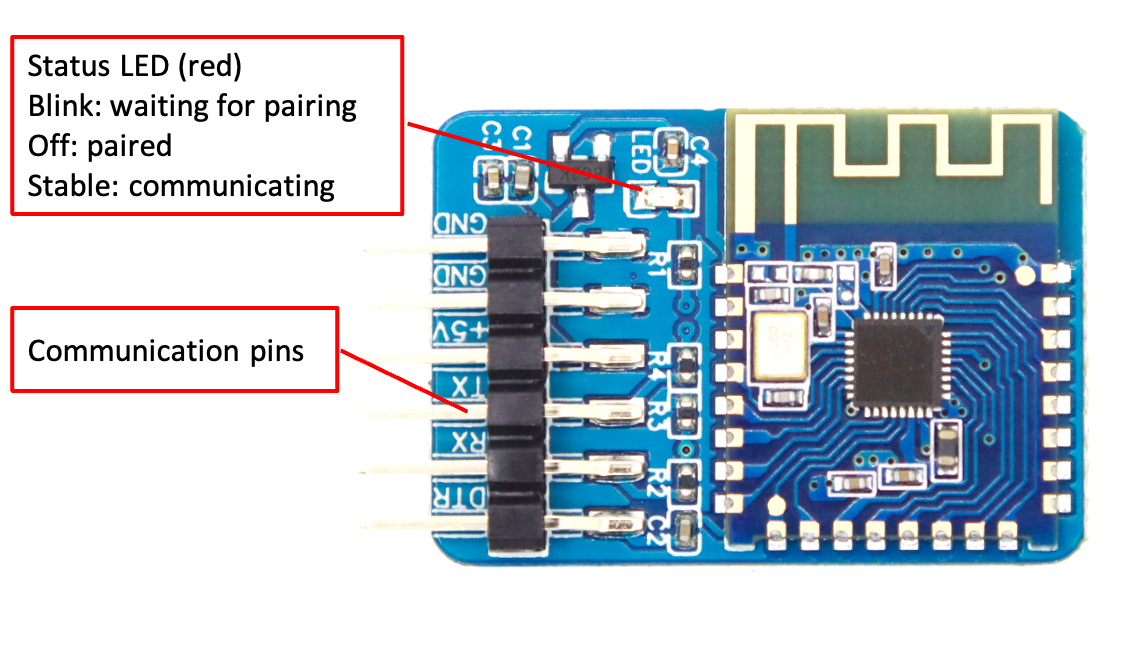

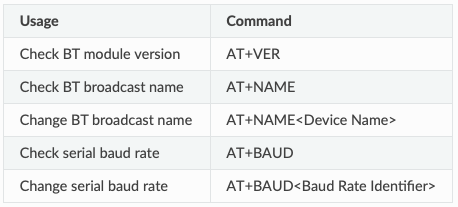
To externally configure bluetooth adaptor, you can connect the Bluetooth Adaptor with USB Adaptor. To configure the module, use serial monitor with line ending as NL and CR and baud rate as 115200. The commonly used AT commands are given below, for complete list please refer JDY-23’s specification sheet.
8.2.3. WiFi Adaptor
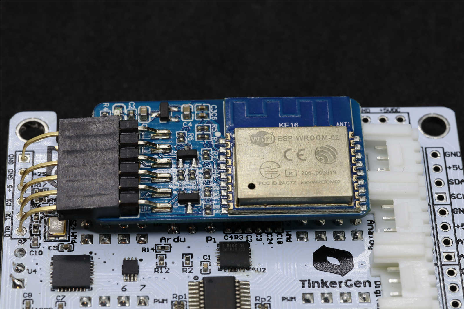
The module uses ESP8266EX’s official model ESP-WROOM-02D, 4MB QSPI Flash. The module includes an automatic download circuit and a communication module. The automatic download circuit refers to the official recommendation to use 2 S8050 transistors to receive the RTS and DTR signals from the CH340C downloader and trigger the download sequence.
To setup the environment for WiFi adaptor, follow the steps below:
In Arduino IDE, open File -> Preferences.
Paste http://arduino.esp8266.com/stable/package_esp8266com_index.json in Additional Boards Manager URL’s section. Click OK and close Preferences Pop-up.
Open Board Manager from Tools -> Board -> Board Manager
Enter ESP8266 in the search bar in Board Manager. You will find a search result developed by ESP8266 Community.
Click on Install. Wait until it finishes.
Once done, select Generic ESP8266 Module from Tools -> Board -> ESP8266 Boards
Select the following settings in Tools menu.
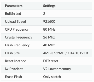
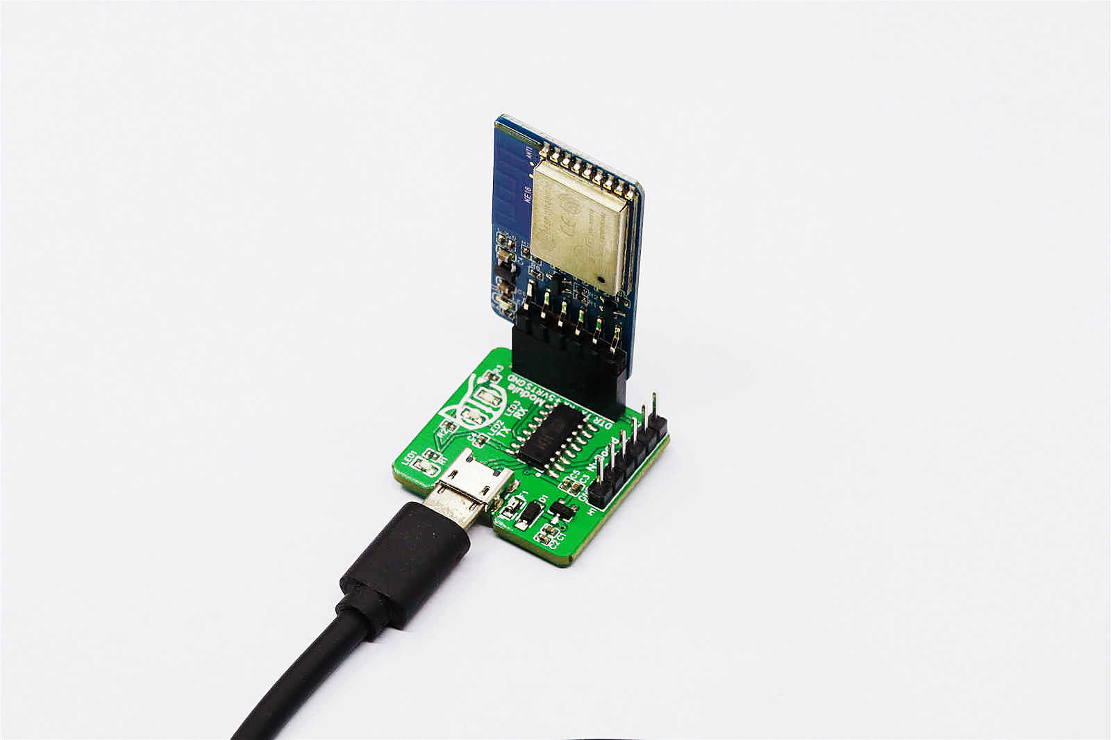
To use the module, a sample code is available under OpenCat/ModuleTests/ESP8266WiFiController. The code folder consists of 3 files:
- ESP8266WiFiController.ino: Arduino sketch with server core code.
- mainpage.h: welcome page (html) in a char array.
- actionpage.h: action controller page (html) in a char array.
Steps to use sample code:
- Open code with IDE. Set the parameters for ESP9266 as given above. Connect the ESP8266 to USB Module.
- Upload the code. Open Serial Monitor and set line ending to NL and CR and baud rate as 115200.
- The module will create a Access Point. Using a WiFi enabled device (Mobile, Tablet, PC etc.), connect to the access point named Bittle-AP.
- Once WiFi is connected, open a web browser and enter 192.168.4.1 in address bar and go to it.
- Here, configure your WiFi so that this ESP8266 can connect to it and thus to Internet.
- After the WiFi connection between your router and ESP8266 is successful, the AP mode will switch to client mode and now your ESP8266 can connect to Internet.
- Enter the IP address shown on Serial Monitor in address bar of your WiFi device. A webpage with various options will open. From here you can control your robot over WiFi.
Additional information about this is provided in a separate section to keep this short. You can read about it here Controlling Bittle (Advanced).
8.3. Imaging Module
In addition to above mentioned modules, you can use a Camera module with Bittle to see what your robot dog is seeing.
For this, an ESP32 Camera module is suitable.
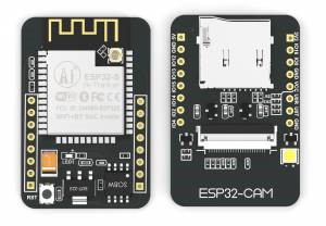
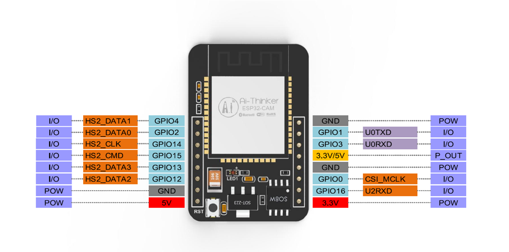
To setup the environment for ESP32 Camera, follow the steps below:
In Arduino IDE, open File -> Preferences.
Paste https://raw.githubusercontent.com/espressif/arduino-esp32/gh-pages/package_esp32_index.json in Additional Boards Manager URL’s section. Click OK and close Preferences Pop-up.
Open Board Manager from Tools -> Board -> Board Manager
Enter ESP32 in the search bar in Board Manager. You will find a search result developed by esp32.
Click on Install. Wait until it finishes.
Once done, select AI Thinker ESP32-CAM from Tools -> Board -> ESP32 Arduino
Select the following settings in Tools menu.

Pin Connection with USB Adapter
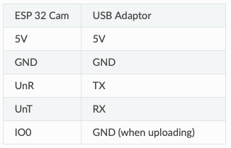
Steps to use sample code:
- Open code with IDE. Open Example file named CameraWebServer from File -> Examples -> ESP32 -> Camera -> CameraWebServer
- Set the credentials for your WiFi, (SSID and Password)
- Please confirm that CAMERA_MODEL_AI_THINKER is selected in the code as this is our board.
- Connect the ESP32_Cam module with the FTDI programmer if not already done. Connect the complete setup to PC using USB cable.
- Select correct COM port and Upload the code. While uploading, keep in mind that GPIO 0 has to connect to GND and module has to reset to go in download mode before you upload code to it.
- After successful upload, disconnect GPIO 0 from GND.
- Open Serial Monitor. Set the Baud Rate to 115200.
- Note the IP-Address and open it in a browser.
- Use onscreen options to control the camera and adjust its parameters.
To use Flash / On board LED, please refer the in lecture presentation for code snippets.
Note
If the upload fails, check in serial monitor if your esp32cam is in download mode (baud rate: 115200).
If it is in download mode, upload again and when you see dots (…) in output window, press reset button on esp32cam.
If you face problems for more than 30 minutes, contact your instructor.
9. Serial Commands Cheat Sheet
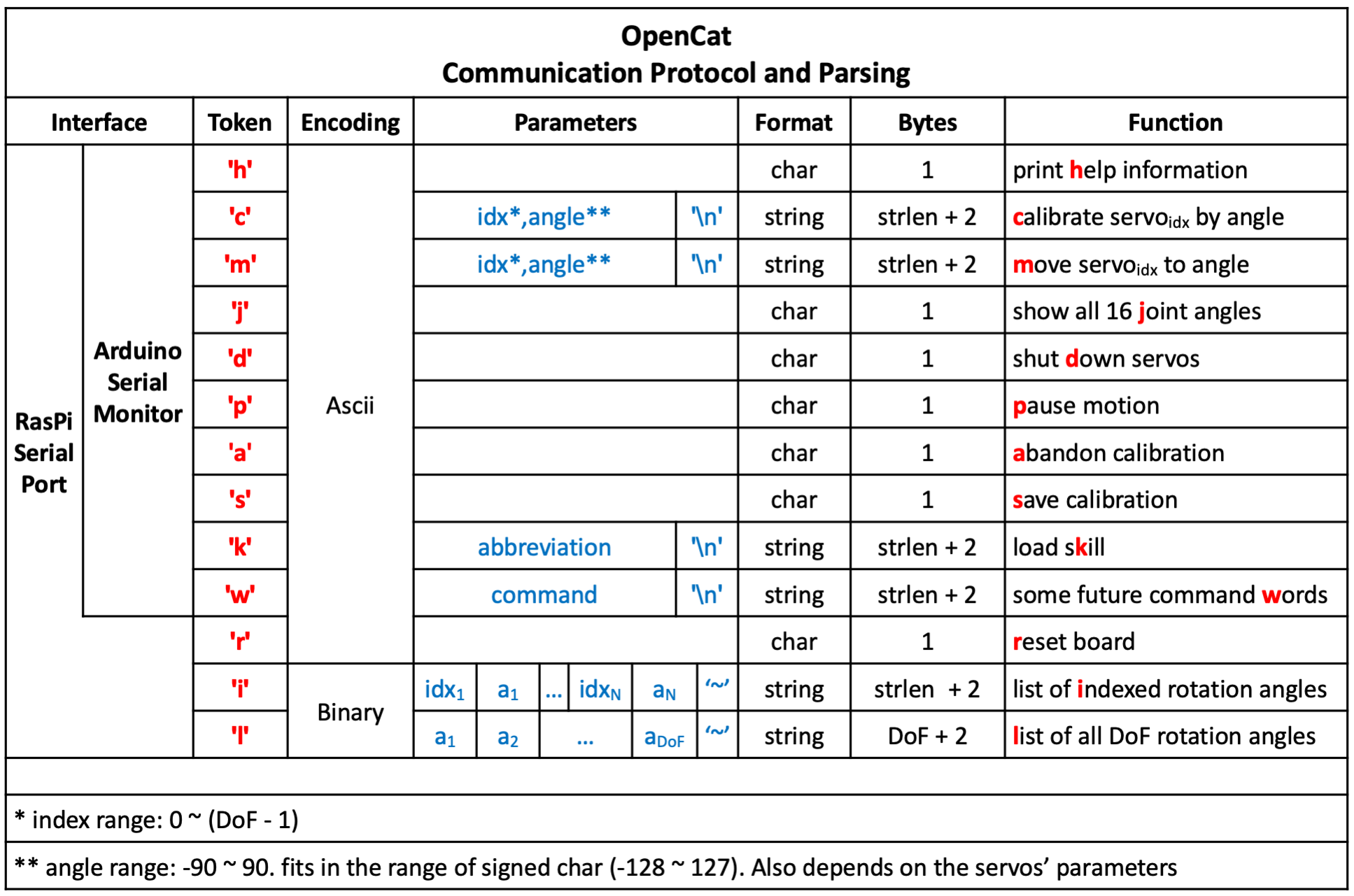
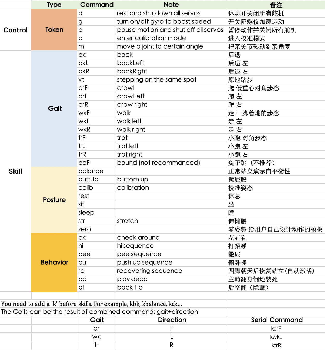
10. Tasks
Before doing the tasks, please make sure that you can control the robot using IR Remote. You should also know how to use Serial commands using Arduino Serial Monitor.
You might need to 3D print some parts to mount your sensors.
These tasks will use Arduino UNO as higher-level controller and the Bittle board as low-level controller. You must upload all your codes only to Arduino UNO. All sensors and actuators must be connected to Arduino UNO and not directly to Bittle board.
Use Serial baud rate as 15200 for communicating with Bittle Board.
You can use SoftwareSerial for the following tasks. Look about this before using.
Warning
Use develop branch for all initial codes. Create other branches according to the requirements.
When everything is ready before submission, merge the code to main branch.
WHEN MERGING develop TO main DE-SELECT “Delete source branch when merge request is accepted.” OPTION.
10.1. Connections
Connect your Bittle with Arduino UNO / ESP32 CAM using TX and RX pins. The connection should be as below:
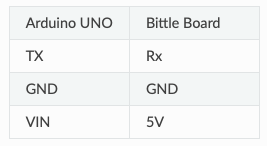
When uploading code, you might have to remove the TX and RX pins from Arduino UNO board as they are connected to the USB programmer.
You can also use Software Serial to virtually create TX and RX on any available digital pin on UNO board.
10.2. Task 1
Make Bittle move straight for some distance, perform a skill, turn around and return back to the start point. The command must start from Node-RED.

10.3. Task 2
Bittle follows a line. The line will have curves, and will not be always straight.
Using ESP32CAM, you must make Bittle follow a line. The line will be White line on a Black (dark) floor.

10.4. Final Task
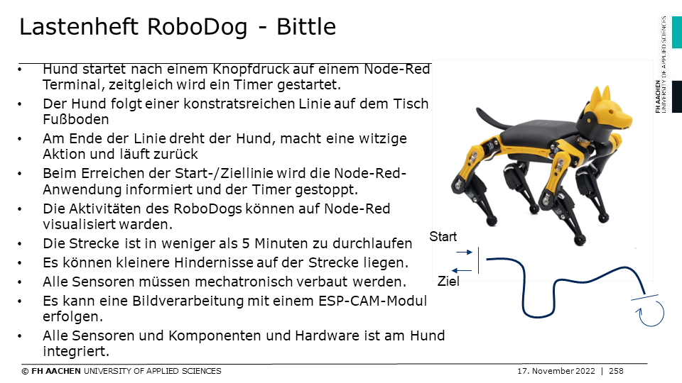
Additionally:
- Doxygen based code document
- Working Video
- Gitlab repository of codes shared with instructor
11. Teach Bittle New Skills
11.1. Understand skills in InstinctBittle.h.
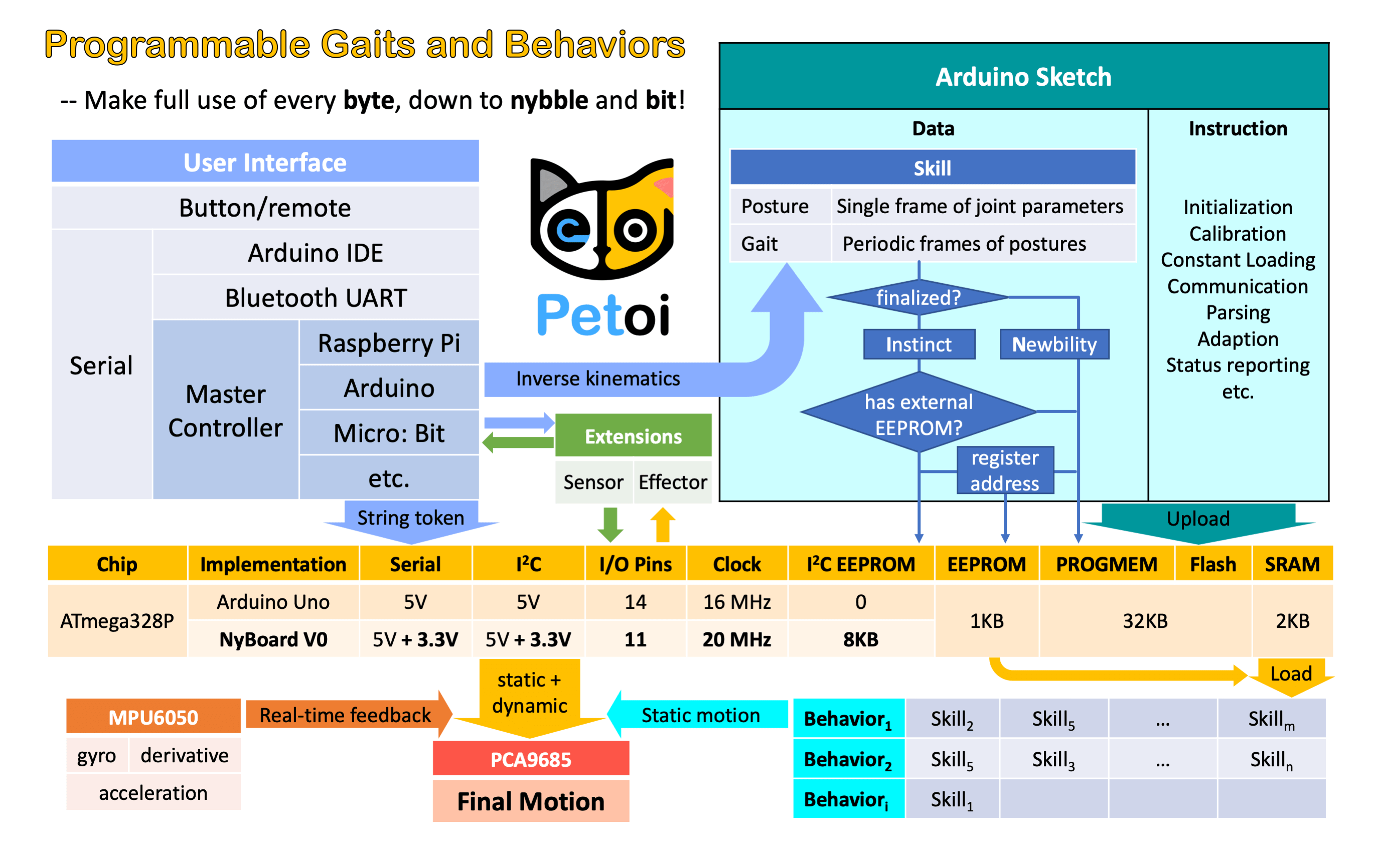
EEPROM has limited (1,000,000) write cycles. So I want to minimize the write operations on it.
There are two kinds of skills: Instincts and Newbility. The addresses of both are written to the onboard EEPROM(1KB) as a lookup table, but the actual data is stored at different memory locations:
I2C EEPROM (8KB) stores Instincts. The Instincts are already fine-tuned/fixed skills. You can compare them to "muscle memory". Multiple Instincts are linearly written to the I2C EEPROM only once with WriteInstinct.ino. Their addresses are generated and saved to the lookup table in onboard EEPROM during the runtime of WriteInstinct.ino.
PROGMEM (sharing the 32KB flash with the sketch) stores Newbility. A Newbility is any new experimental skill that requires a lot of tests. It's not written to the I2C nor onboard EEPROM, but the flash memory in the format of PROGMEM. It has to be uploaded as one part of the Arduino sketch. Its address is also assigned during the runtime of the code, though the value rarely changes if the total number of skills (including all Instincts and Newbilities) is unchanged.
11.2. Example InstinctBittle.h
//a short version of InstinctBittle.h as example

#define BITTLE
#define NUM_SKILLS 4
#define I2C_EEPROM

const char rest[] PROGMEM = {
1, 0, 0, 1,
-30, -80, -45,   0,  -3,  -3,   3,   3,  75,  75,  75,  75, -55, -55, -55, -55,};
const char zero[] PROGMEM = {
1, 0, 0, 1,
    0,   0,   0,   0,   0,   0,   0,   0,   0,   0,   0,   0,   0,   0,   0,   0,};

const char crF[] PROGMEM = {
36, 0, -3, 1,
61,  68,  54,  61, -26, -39, -13, -26,
66,  61,  58,  55, -26, -39, -13, -26,
...
51,  81,  45,  72, -25, -37, -12, -25,
55,  76,  49,  68, -26, -38, -13, -26,
60,  70,  53,  62, -26, -39, -13, -26,
};

const char pu[] PROGMEM = {
-8, 0, -15, 1,
6, 7, 3,
0,   0,   0,   0,   0,   0,   0,   0,  30,  30,  30,  30,  30,  30,  30,  30,        5, 0,
15,  0,   0,   0,   0,   0,   0,   0,  30,  35,  40,  29,  50,  15,  15,  15,        5, 0,
30,  0,   0,   0,   0,   0,   0,   0,  27,  35,  40,  60,  50,  15,  20,  45,        5, 0,
15,  0,   0,   0,   0,   0,   0,   0,  45,  35,  40,  60,  25,  20,  20,  60,        5, 0,
0,   0,   0,   0,   0,   0,   0,   0,  50,  35,  75,  60,  20,  30,  20,  60,        6, 0,
-15, 0,   0,   0,   0,   0,   0,   0,  60,  60,  70,  70,  15,  15,  60,  60,        6, 0,
0,   0,   0,   0,   0,   0,   0,   0,  30,  30,  95,  95,  60,  60,  60,  60,        6, 1,
30,  0,   0,   0,   0,   0,   0,   0,  75,  70,  80,  80, -50, -50,  60,  60,        8, 0,
};

#if !defined(MAIN_SKETCH) || !defined(I2C_EEPROM)
const char* skillNameWithType[] =
{"crI", "puI", "restI", "zeroN",};
const char* progmemPointer[] =
{cr, pu, rest, zero, };
#else
const char* progmemPointer[] = {zero};
#endif
11.2.1. Defined constants
define WalkingDOF 8defines the number of DoF (Degree of Freedom) for walking is 8 on Bittle.
define NUM_SKILLS 4defines the total number of skills is 4. It should be the same as the number of items in the list const char* skillNameWithType[].
define I2C_EEPROMMeans there's an I2C EEPROM on NyBoard to save Instincts.
If you are building your own circuit board that doesn't have it, comment out this line. Then both kinds of skills will be saved to the flash as PROGMEM. Obviously, it will reduce the available flash space for functional codes. If there were too many skills, it may even exceed the size limit for uploading the sketch.
11.2.2. Data structure of skill array
One frame of joint angles defines a static posture, while a series of frames defines sequential postures, such as a gait or a behavior. Observe the following two examples:
const char rest[] PROGMEM = {
1, 0, 0, 1,
-30, -80, -45,   0,  -3,  -3,   3,   3,  75,  75,  75,  75, -55, -55, -55, -55,};

const char crF[] PROGMEM = {
36, 0, -3, 1,
61,  68,  54,  61, -26, -39, -13, -26,
66,  61,  58,  55, -26, -39, -13, -26,
...
51,  81,  45,  72, -25, -37, -12, -25,
55,  76,  49,  68, -26, -38, -13, -26,
60,  70,  53,  62, -26, -39, -13, -26,
};
They are formatted as:

rest is a static posture, it has only one frame of 16 joint angles. crF is the abbreviation for "crawl forward". It has 36 frames of 8 (or 12, depending on the number of walking DOF) joint angles that form a repetitive gait. Expected body orientation defines the body angle when the robot is conducting the skill. If the body is tilted from the expected angles, the balancing algorithm will calculate some adjustments. Angle ratio is used when you want to store angles larger than the range of -128 to 127. Change the ratio to 2 so that you can save those large angles by dividing 2.
A posture has only one frame, and a gait has more than one frames and will be looped over.
The following example is a behavior:
const char pu[] PROGMEM = {
-8, 0, -15, 1,
6, 7, 3,
0,    0,   0,   0,   0,   0,   0,   0,  30,  30,  30,  30,  30,  30,  30,  30,       5, 0, 0, 0,
15,   0,   0,   0,   0,   0,   0,   0,  30,  35,  40,  29,  50,  15,  15,  15,       5, 0, 0, 0,
30,   0,   0,   0,   0,   0,   0,   0,  27,  35,  40,  60,  50,  15,  20,  45,       5, 0, 0, 0,
15,   0,   0,   0,   0,   0,   0,   0,  45,  35,  40,  60,  25,  20,  20,  60,       5, 0, 0, 0,
0,    0,   0,   0,   0,   0,   0,   0,  50,  35,  75,  60,  20,  30,  20,  60,       6, 0, 0, 0,
-15,  0,   0,   0,   0,   0,   0,   0,  60,  60,  70,  70,  15,  15,  60,  60,       6, 0, 0, 0,
0,    0,   0,   0,   0,   0,   0,   0,  30,  30,  95,  95,  60,  60,  60,  60,       6, 1, 0, 0,
30,   0,   0,   0,   0,   0,   0,   0,  75,  70,  80,  80, -50, -50,  60,  60,       8, 0, 0, 0,
};
pu is short for "push up", and is a "behavior". Its data structure contains more information than posture and gait.
The first four elements are defined the same as before, except that the number of frames is saved as a negative value to indicate that it's a behavior. The next three elements define the repeating frames in the sequence: starting frame, ending frame, looping cycles. So the 6, 7, 3 in the example means the behavior should loop from the 7th to the 8th frame for 3 times (the index starts from 0). The whole behavior array will be executed only once, rather than looping over like the gait.
Each frame contains 16 joint angles, and the last 4 elements define the speed of the transition, and the delay condition after each transition:
The default speed factor is 4, it can be changed to an integer from 1 (slow) to 127 (fast). The unit is degree per step. If it's set to 0, the servo will rotate to the target angle by its maximal speed (about 0.07sec/60 degrees). It's not recommended to use a value larger than 10 unless you understand the risks.
The default delay is 0. It can be set from 0 to 127, the unit is 50 ms.
The 3rd number is the trigger axis. If it's not 0, the previous delay time will be ignored. The trigger of the next frame will depend on the body angle on the corresponding axis. 1 for the pitch axis, and 2 for the roll axis. The sign of the number defines the direction of the threshold, i.e. if the current angle is smaller or larger than the trigger angle.
The 4th number is the trigger angle. It can be -128 to 127 degrees.
11.2.3. Suffix for indicating Instinct and Newbility
You must upload WriteInstinct.ino to have the skills written to EEPROM for the first time. The following information will be used:
const char* skillNameWithType[] =
{"crI", "puI", "restI", "zeroN",};
const char* progmemPointer[] =
{cr, pu, rest, zero, };
Notice the suffix I or N in the skill name strings. They tell the program where to store skill data and when to assign their addresses.
Later, if the uploaded sketch is the main sketch OpenCat.ino, and if you are using NyBoard that has an I2C EEPROM, the program will only need the pointer to the Newbility list
const char* progmemPointer[] = {zero};to extract the full knowledge of pre-defined skills.
11.3. Define new skills and behaviors
11.3.1. Modify the existing skill template
There's already a skill called "zeroN" in InstinctBittle.h. It's a posture at the zero state waiting for your new definition. You can first use the command mIndex Offset to move an individual joint to your target position, then replace the joint angles (bold fonts) in array at once:
const char zero[] PROGMEM = {
1, 0, 0, 1,
0,  0,  0,  0,  0,  0,  0,  0,  0,  0,  0,  0,  0,  0,  0,  0,};
Because it's declared as a Newbility and doesn't require writing to I2C EEPROM, you can simply upload OpenCat.ino every time you change the array (without uploading WriteInstinct.ino). You can trigger the new posture by pressing 7> on the IR remote, or type kzero in the serial monitor.
You can rename this skill, but remember to update the keymap of the IR remote.
11.3.2. Add more skills in InstinctBittle.h
You can add more skills in InstinctBittle.h. Remember to increase the skill number at the beginning of the file and add the corresponding skill name and pointer in the skill list array.
A skill can be called from the serial monitor with the token 'k' command. For example, ksit will move Bittle to posture "sit".
You can also tune new skills by sending posture frames through the serial port, using the m, i, l tokens without uploading a new sketch. After fine-tuning the skill, you can save it in the instinctBittle.h and upload it to the board as a newbility or instinct.
Always check the actual code for the available skill names. We may alter the skill set as we iterate the software.
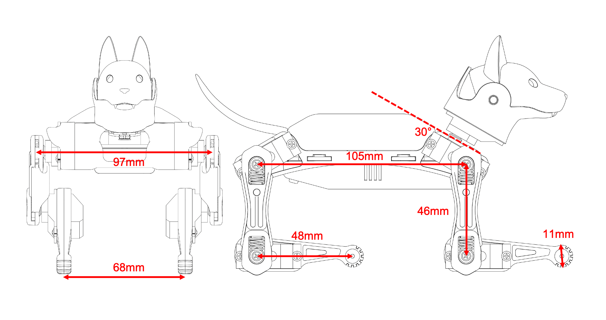
This git repo ( https://github.com/ger01d/kinematic-model-opencat ) is a good starting point if you want to develop a customized gait. If you are going to do some inverse kinematics calculation, you may use the following key dimensions to build your model.
11.3.3. Automation
So far Bittle is controlled by the infrared remote. You make decisions for Bittle's behavior.
You can connect Bittle with your computer or smartphone, and let them send out instructions automatically. Bittle will try its best to follow those instructions.
By adding some sensors (like a touch sensor), or some communication modules (like a voice control module), you can bring new perception and decision abilities to Bittle. You can accumulate those automatic behaviors and eventually make Bittle live by itself!
Another direction is to set up a simulation for Bittle then test the model in reality. You may use this Unified Robot Description Format (URDF) ( https://github.com/AIWintermuteAI/Bittle_URDF ) file for Bittle to set up an NVIDIA Omniverse simulation.
11.4. Understand OpenCat.h
The controlling framework behind Bittle is OpenCat, which I've been developing for a while. You can learn more from posts available here ( https://www.hackster.io/petoi/opencat-845129 )
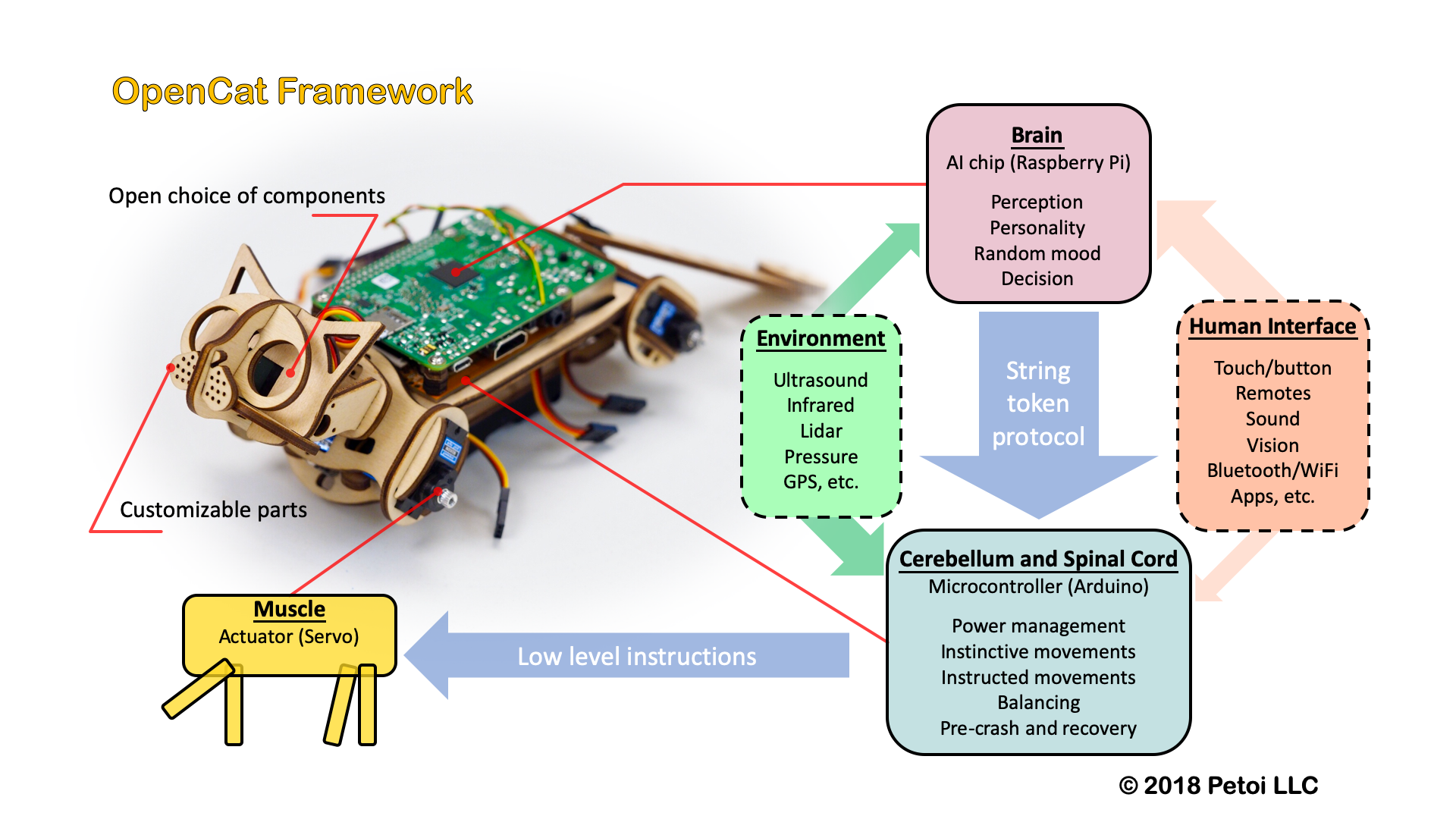
Further reading abut code review: ( https://www.petoi.camp/forum/software/flavien-opencat-code-reviews )
11.5. Tutorial on Creating New Skills
11.5.1. Preparation
Get familiar with the standard process of assembly, uploading the standard program Opencat.ino, and calibration.
Validate that the following functions work as expected.
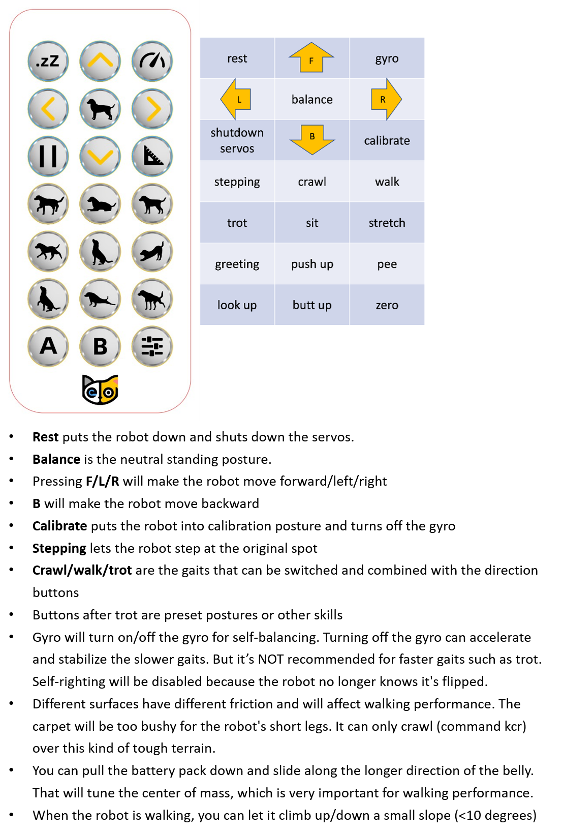
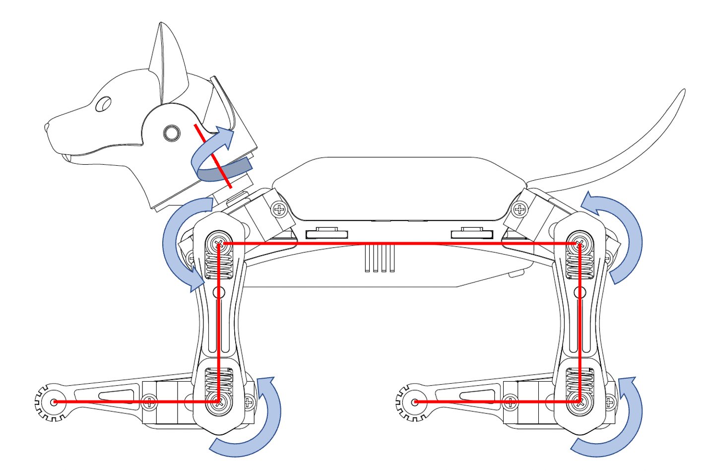
Press the button which is in the 2nd row, the 2nd column on the IR remote. Later we will use (2, 2) as the index. You can also enter kbalance via serial port. Bittle should stand up and keep balance;
Press the button which is in the 7th row, the 3rd column on the IR remote. Later we will use (7, 3) as the index. You can also enter kzero via serial port. Bittle should enter a posture similar to the calibration state, which is the "zero" skill in the program (as shown in the figure below).
Open the folder src/, create a backup file of instinctBittle.h as instinctBittle.hBAK.
The coordinate system of Bittle is shown in the figure below.
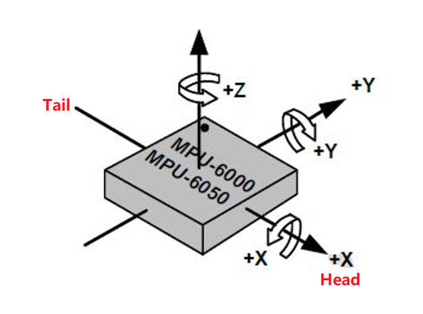
Yaw: Rotate around the Z-axis.
Pitch: Rotate around the Y-axis (nose up/down).
Roll: Rotate around the X-axis (tilt left/right).
For the legs, on the left side, counterclockwise is positive, clockwise is negative. On the right side, the rotation directions are mirrored. The origin position and rotation direction of a single leg (upper/lower leg) around the joint are shown in the 2nd figure.
The indexing order of all the joints is shown in the figure below:
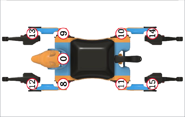
The skill arrays are defined in WriteInstinct/instinctBittle.h, formatted as the figure below. Note the index starts from 0.

Total # of Frames defines the number of frames of a certain skill.
For example, rest is a static posture, it has only one frame of 16 joint angles.
crF is the abbreviation for "crawl forward". It has 36 frames of 8 (or 12, depending on the number of walking DOF) joint angles that form a repetitive gait.
Expected body orientation defines the body angle when the robot is conducting the skill. When all joints move to their corresponding joint angle values in the current frame, the body inclination should naturally reach the defined expected angle. If the body inclination deviates from the expected angle, the balance algorithm will calculate some adjustment values for each leg servo , in order to keep the body tilt as close to the expected angle as possible.
Angle ratio is used when you want to store angles larger than the range of -128 to 127. Change the ratio to 2 so that you can save those large angles by dividing 2.
11.5.2. Understand the format of a posture
Zero is a static posture, Find the zero array in instinctBittle.h:
const char zero[] PROGMEM = {
1, 0, 0, 1,
0,   0,   0,   0,   0,   0,   0,   0,   0,   0,   0,   0,   0,   0,   0,   0,};
Change some of these values to:
const char zero[] PROGMEM = {
1, 0, 0, 1,
70, 0, 0, 0, 0, 0, 0, 0, -60, 0, 0, 0, 60, 0, 0, 0,};
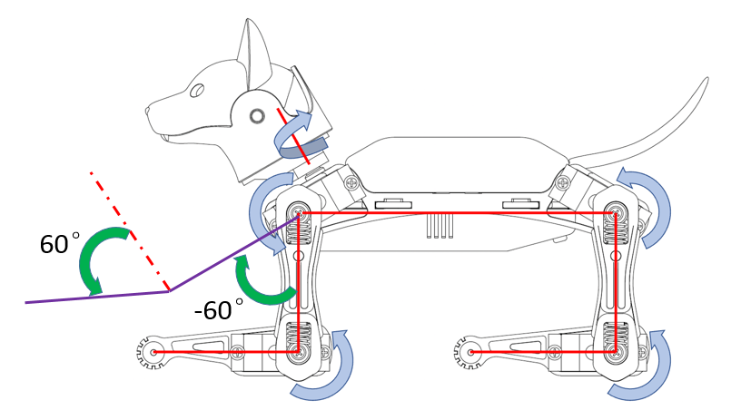
Save the change, and upload the program OpenCat.ino to Bittle (Note: there is no need to upload writeinsict.ino or opencat.h), after upload, press the button (9) which is in the 7th row, the 3rd column on the IR remote to trigger the modified zero skill. You can see the posture is changed.
The new zero pose looks like this:
The first element (1) represents the total number of frames of the skill, 1 means it is a static posture.
The 4th element (1) represents the Angle ratio. It means all the following indexed joint angles are actual angles (because each of them multiply by 1).
From the 5th to the 20th elements represent 16 indexed joint angles.
For Bittle, the 5th element (joint index 0) means the servo on Bittle's neck rotates counterclockwise 70 (the unit is in degrees). Bittle's head turn to it's left side.
The 13th element (joint index 8) means Bittle's left upper leg rotates clockwise 60 (the unit is in degrees) around the joint.
The 17th element (joint index 12) means Bittle's left lower leg rotates counterclockwise 60 (the unit is in degrees) around the joint.
All the other indexed joint angles remain 0 (the unit is in degrees).
You can define a new posture and upload it to the robot. Call the new posture with the IR remote or the serial monitor.
11.5.3. Explain expected body orientations
Look at the example of:
const char balance[] PROGMEM = {
1, 0, 0, 1,
0,   0,   0,   0,   0,   0,   0,   0,  30,  30,  30,  30,  30,  30,  30,  30,};
and
const char sit[] PROGMEM = {
1, 0, -30, 1,
0,   0, -45,   0,  -5,  -5,  20,  20,  45,  45, 105, 105,  45,  45, -45, -45,};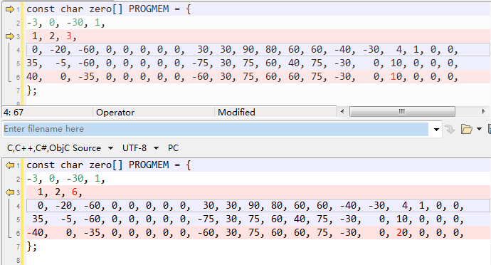
The 2nd and 3rd elements represent Expected body orientation, corresponding to the roll angle and the pitch angle.
The unit is in degrees.
The sign of the number follows the right-handed spiral rule, look along the direction pointed by the axis arrow, clockwise is positive, counterclockwise is negative.
With the gyro activated, rotate Bittle, when the body is tilted from the expected angles, the balancing algorithm will calculate some adjustments to keep it in this posture.
11.5.4. Explain angle ratio
Look at the example of
const char rc[] PROGMEM = {
-3, 0, 0, 2,
0, 0, 0,
0,    0,   0,   0,   0,   0,   0,   0, -88, -43,  67,  87,  42, -35,  42,  42,      15, 0, 0, 0,
0,    0,   0,   0,   0,   0,   0,   0, -83, -88,  87,  42,  42,  42,  42, -40,      15, 0, 0, 0,
-8, -20, -11,   0,  -1,  -1,   0,   0,  18,  18,  18,  18, -14, -14, -14, -14,      10, 0, 0, 0,
};
Angle ratio is designed for large angles out of the range -128~127.
The 4th element (2) represents the angle ratio. It means all the following all indexed joint angles real values is equal to each of them multiply by the value of this angle ratio.
11.5.5. Understand the format of a gait
A series of frames defines sequential postures, such as a gait. Find the bk array in instinctBittle.h:
bk is the abbreviation for "back".
The first four elements are defined the same as before, The first element (35) means it has 35 frames. Next are 35 frames of 8 indexed joint angles that form a repetitive gait.
11.5.6. Understand the format of a behavior
Modify the zero skill as:

Upload the new zero skill and see the effect. It should be the same. (Later explanation a posture can be considered as a behavior or gait with one frame.)
Copy the content of hi array to zero:
Change a few values:

Save and upload OpenCat.ino. Call the new zero skill to see the effect.
For example, the modified hi behavior:
The first four elements are defined the same as before, except that the number of frames is saved as a negative value (-3) to indicate that it's a behavior.
The 2nd element (0) means the Roll rotation body angle is 0 (The unit is in degrees). The 3rd element (-30) means the Pitch rotation body angle is -30 (The unit is in degrees). If the body is tilted from the expected angles, the balancing algorithm will calculate some adjustments. The 4th element (1) means all the following all indexed joint angles are real values.
The next three elements define the repeating frames in the sequence: starting frame (1), ending frame (2), looping cycles (6). So the 1, 2, 6 in the example means the behavior should loop from the 2nd to the 3rd frame for 6 times (the index starts from 0). The whole behavior array will be executed only once, rather than looping over like the gait.
For behavior, each frame contains 16 indexed joint angles, and the last 4 elements define the speed of the transition, and the delay condition after each transition:
The first number represents speed factor. The default speed factor is 4, it can be changed to an integer from 1 (slow) to 127 (fast). The unit is in degrees per step. If it's set to 0, the servo will rotate to the target angle by its maximal speed (about 0.07sec/60 degrees). It's not recommended to use a value larger than 10 unless you understand the risks. Here for this example, in the first frame, it is default value (4).
The 2nd number represents delay time. The default delay is 0. It can be set from 0 to 127, the unit is 50 ms. Here for this example, in the first frame, it is 1.
The 3rd number represents the trigger axis. If it's not 0, the previous delay time will be ignored. The trigger of the next frame will depend on the body angle on the corresponding axis. 1 for the pitch axis, and 2 for the roll axis. The sign of the number defines the direction in which the threshold is exceeded. In the first frame of this example, it is 0, which means this trigger condition is not enabled.
The 4th number represents the trigger angle. It can be -128 to 127 degrees. The use of this value needs to be combined with the third number. Only when the robot body rotates in the specified direction exceeds this trigger angle, the action of the next frame can be triggered. In the first frame of this example, it is 0. If the third number is 0, it means that the trigger condition is not enabled, and this value is invalid.
11.5.7. Understand the memory structure
Explanation the locations:
There are two kinds of skills: Instincts and Newbility. The addresses of both are written to the onboard EEPROM(1KB) as a lookup table, but the actual data is stored at different memory locations:
I2C EEPROM (8KB) stores Instincts. The Instincts are already fine-tuned/fixed skills. You can compare them to "muscle memory". After uploading the "parameters" firmware, multiple instinctive Instincts write linearly to the I2C EEPROM. Their addresses are generated during the upload of the "parameters" firmware and saved to a lookup table in the onboard EEPROM.
Flash (sharing the 32KB flash with the program) stores Newbility. A Newbility is any new experimental skill that requires a lot of tests. It's not written to the I2C nor onboard EEPROM, but the flash memory in the format of PROGMEM. It has to be uploaded as one part of the Main function firmware. Its address is also assigned during the runtime of the code, though the value rarely changes if the total number of skills (including all Instincts and Newbilities) is unchanged.
The implementation code:
The first section is active when uploading "parameters" firmware. It contains all the skills' data and pointers. The skill names contain a suffix, "N" or "I" to indicate whether it's a Newbility or Instinct. The Instinct will be saved to the external I2C EEPROM while the Newbility will be saved to the flash. The address of all the skills will be saved to the onboard EEPROM.
The second section is active when uploading Main function firmware. Because the Instincts are already saved in the external EEPROM, their data is omitted to save space. The Newbility will be saved to the flash with the upload so you can update them in the MAIN_SKETCH section . It's very useful if you are still tuning a new skill.
In the example code, only zero is defined as a Newbility so you don't need to re-upload "parameters" firmware for experiments.
11.5.8. Create a new behavior
What if we want to add more skills with customized names and button assignments?
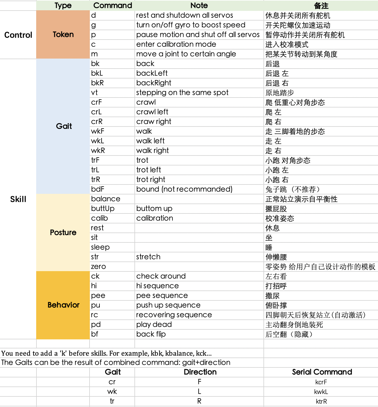 If you want to add more skills, you can refer to the implementation of serial commands (the figure above) and keymap (the 1st figure) in the program code.
Add an example of a Newbility test and assign it to a button on the IR remote. Upload the skill and call it with both IR remote and serial monitor.
Modify a few fields of test to make it an Instinct. Call the behavior with the IR remote or serial monitor.
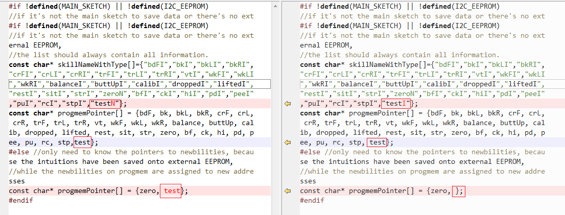
The left side of the above picture is to add a new skill (Newbility); the right side is to add a new instinct (Instinct). Remember to add 1 to the number of skills at the beginning of the header file.
Then you can call this test by entering ktest in the serial monitor. You can also call it from the IR remote if you replace a button definition in OpenCat.h.
11.5.9. Tune skills in realtime
You need to understand the above structure to store a skill on the robot. However, when tuning the skills, things can be easier. To do this, you can connect your computer with the robot through the USB or Bluetooth connector. Then you can send string commands that define the joint angles. The program on the NyBoard will listen and perform the instructions in real-time. In the folder SerialMaster , you can find the ardSerial.py to play the role of Arduino IDE's serial monitor, and you can also write scripts to control Bittle to do more complex movements. Some use cases are listed in example.py.
Please refer to Controlling with Python section for more details.
