Bittle Advanced and Troubleshooting
12. Controlling Bittle (Advanced)
CONTENT UNDER REVIEW. Please ask the instructor before continuing with this section.
This section will described advanced methods to control your robot.
12.1. Using WiFi Adaptor
About the Sample Code: The sample code is a simple web server example, including 2 HTML pages. The two pages are stored in two header files in the form of string constants. The advantage is to avoid calling the client.print function constantly.
Set Up the WiFi Networks: Before we start our web server, we should configure the WiFi to connect to your local area network(LAN). We used to enter the WiFi SSID and password in the program, but it is very inconvenient while we need to change the network environment. We use the WiFi manager library to configure the WiFi information through web.
// WiFiManager
WiFiManager wifiManager;

// Start WiFi manager, default gateway IP is 192.168.4.1
wifiManager.autoConnect("Bittle-AP");
Web server: Create a new web server and configure port 80 (commonly used HTTP server port)
ESP8266WebServer server(80);Configure 3 HTTP service handler: The HTTP response function is to handle the incoming HTTP requests.
void handleMainPage() {
//Serial.println("GET /");
server.send(200, "text/html", mainpage);
}
void handleActionPage() {
//Serial.println("GET /actionpage");
server.send(200, "text/html", actionpage);
}
The handleMainPage and handleActionPage response 200 (OK) and corresponding web HTML code for your web browser (client).
void handleAction(){
String argname = server.arg("name");

if(argname == "gyro"){              // gyro switch
    Serial.print("g");
}
The HandleAction function is slightly different. This is an HTTP request processing function with parameter passing. When the parameter is "gyro", the serial port of the WiFi module sends out the command ("g", switch IMU), so that our Bittle will execute the command. So how is this "gyro" parameter generated and passed? Because we sent such an HTTP request with a value to the server:
http://IP address or DomainName/action?name=gyroThe server parses the action parameter by the function and resolves that the name is "gyro". We can directly enter this URL in the browser and execute it with the keyboard. The more common method is to add a link to the "Walk" button on the ActionPage web page. When the gyro button is pressed, the above URL will be sent to the host. The complete walk button configuration is as follows:
<button style="width: 25%" onclick="location.href='/action?name=gyro'">GyroOn/Off</button>After parsing the "name" parameter, we send the actionpage again.
server.send(200, "text/html", actionpage);We bond the handler method with the corresponding URLs.
server.on("/", handleMainPage);
server.on("/actionpage", handleActionPage);
server.on("/action", handleAction);
Start the Web Server:
server.begin();
Serial.println("HTTP server started");
Handle Client Requests:
void loop(void){
server.handleClient();
}
12.2. Using Python Scripts
The list testSchedule in example.py is used to test various serial port commands. Run the following script code to see the execution effect of each serial port command in the list:
for task in testSchedule:
wrapper(task)
You can also refer to the content of the stepUpSchedule list (in ..\serialMaster\demos\stepup.py), write a list of behaviors according to your actual needs, and realize your creativity.
Note: When running the scripts under the path of serialMasterdemos, you must first use the "cd demos" command to enter the path where the scripts are located (\serialMaster\demos), and then use the python3 command to run the script (e.g. python3 stepup.py)
Explanation of the serial port commands in the list testSchedule:
['kbalance', 2]'kbalance' indicates the command to control Bittle to stand normally 2 indicates the postponed time after finishing the command, in seconds
['d', 2]d indicates the command to put the robot down and shut down the servos 2 indicates the postponed time after finishing the command, in seconds
['c', 2]c indicates the command to enter calibration mode 2 indicates the postponed time after finishing the command, in seconds. After these motion commands are completed, the next command will be executed after a 2-second delay.
['c', [0, -9], 2]c indicates the command to enter calibration mode 0 indicates the index number of joint servo -9 indicates the rotation angle, the unit is degree 2 indicates the postponed time after finishing the command, in seconds
Using this format, you can enter the calibration mode to calibrate the angle of a certain joint servo. Note: If you want the correction value in this command to take effect, you need to enter the "s" command after executing this command.
The meaning of this example: the joint servo with serial number 0 rotates -9 degrees. After these motion commands are completed, the next command will be executed after a 2-second delay.
['m', [0, -20], 1.5]m indicates the command to control the rotation of the joint servo 0 indicates the index number of joint servo -20 indicates the rotation angle (this angle refers to the origin, rather than additive) the unit is degree 1.5 indicates the postponed time after finishing the command, in seconds. It can be a float number.
['m', [0, 45, 0, -45, 0, 45, 0, -45], 2]Using this format, multiple joint servo rotation commands can be issued at one time, and these joint servo rotation commands are executed SEQUENTIALLY, not at the same time. The joint angles are treated as ASCII characters, so they can be entered directly by humans.
The meaning of this example is: the joint servo with index number 0 is first rotated to the 45 degree position, and then rotated to the -45 degree position, and so on. After these motion commands are completed, the next command will be executed after a 2-second delay.
['i', [ 8, -15, 9, -20], 2]Using this format, multiple joint servo rotation commands can be issued at one time, and these joint servo rotation commands are executed AT THE SAME TIME. The joint angles are treated as ASCII characters, so they can be entered directly by humans.
The meaning of this example is the joint servos with index numbers 8, 9 are rotated to the -15, -20 degree positions at the same time. After these motion commands are completed, the next command will be executed after a 2-second delay.
['M', [8, 50, 9, 50, 10, 50, 11, 50, 0, 0], 3]M indicates the command to rotate multiple joint servos SEQUENTIALLY. The angles are encoded as BINARY numbers for efficiency. 8, 9, 10, 11, 0 indicate the index numbers of joint servos 50, 50, 50, 50, 0 indicate the rotation angle (this angle refers to the origin, rather than additive ), the unit is degree 3 indicates the postponed time after finishing the command, in seconds
['I', [20, 0, 0, 0, 0, 0, 0, 0, 45, 45, 45, 45, 36, 36, 36, 36], 5]I indicates the command to control all joint servos to rotate AT THE SAME TIME (currently the command supports 16 degrees of freedom, that is, 16 servos) . The angles are encoded as BINARY numbers for efficiency. 20,0,0,0,0,0,0,0,45,45,45,45,36,36,36,36 indicate the rotation angle of each joint servo corresponding to 0-15 (this angle refers to the origin, rather than additive), the unit is degree 5 indicates the postponed time after finishing the command, in seconds
['b', [10,2], 2]b indicates the command to control the buzzer to beep 10 indicates the music tone 2 indicates the lengths of duration, corresponding to 1/duration second 2 indicates the postponed time after completing the tone, in seconds
['b',[0, 1, 14, 8, 14, 8, 21, 8, 21, 8, 23, 8, 23, 8, 21, 4, 19, 8, 19, 8, 18, 8, 18, 8, 16, 8, 16, 8, 14, 4],3]b indicates the command to control the buzzer to beep 0, 14, 14, 21… indicate the music tones 1, 8, 8, 8 indicates the lengths of duration, corresponding to 1/duration second The last 3 indicates the postponed time after the music melody is played, in seconds
Using this format, multiple tone pronunciation commands can be issued at once, and a simple melody can be played.
The meaning of this example is: play a simple melody, and delay 3 seconds after the music melody is played.
ck = [
    -3, 0, 5, 1,
    0, 1, 2,
    45, 0, 0, 0, 0, 0, 0, 0, 45, 35, 38, 50, -30, -10, 0, -20, 6, 1, 0, 0,
    -45, 0, 0, 0, 0, 0, 0, 0, 35, 45, 50, 38, -10, -30, -20, 0, 6, 1, 0, 0,
    0, 0, 0, 0, 0, 0, 0, 0, 30, 30, 30, 30, 30, 30, 30, 30, 5, 0, 0, 0,
    ]
['K', ck, 1]
'K' indicates the skill data to send to Bittle in realtime The skill array is sent to the robot on the go and executed locally on the robot You may insert the skills in the skill library or InstinctX.h in this format
12.3. Creating New Skills


13. Controlling Bittle (Codecraft)
13.1. Introduction
Codecraft is a graphical programming software. It is based on the Scratch 3.0 language and enables programming by simply "drag & drop" of predefined blocks. It is available as a web and downloadable application.
The web version is available at ( https://ide.tinkergen.com/ ). Here you can make codes but to upload to your hardware, you would need a client application for your PC. You can find more information here: ( https://www.yuque.com/tinkergen-help-en/codecraft/assistant?language=en-us )
To download complete software, from the following link: ( https://ide.tinkergen.com/download/en/ ). This includes IDE and uploader for your hardware.
When you open the application, you have to select the hardware you will use for programming. In our case, it's Bittle. After that you will be redirected to the programming UI.
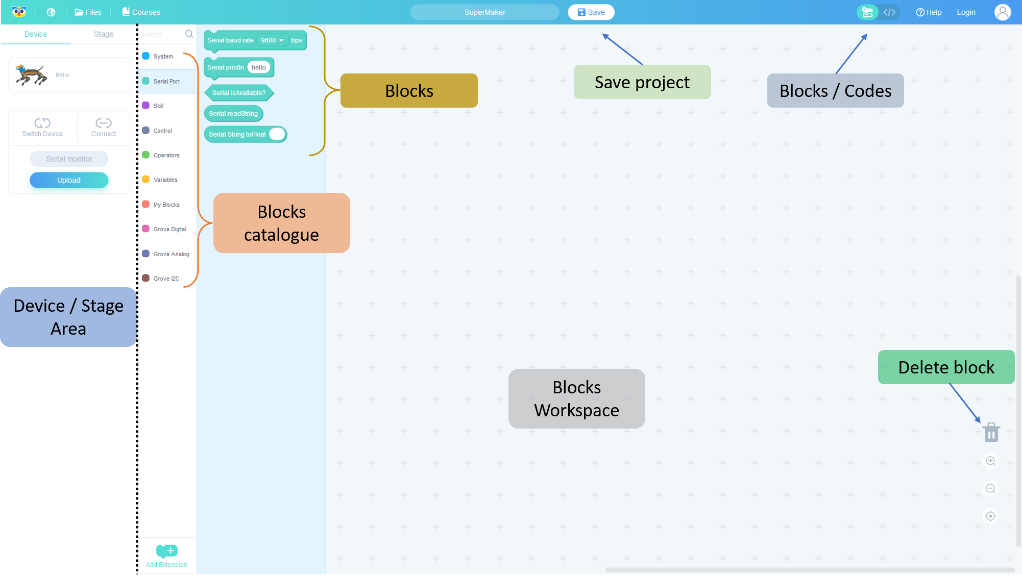
For detailed information about UI elements, visit ( https://www.yuque.com/tinkergen-help-en/codecraft/tour_overview )
Note that Codecraft doesn't support OpenCat 2.0. You'd need to use OpenCat 1.0 instead. You can find the details here: https://github.com/PetoiCamp/OpenCat/tree/1.0
13.1.1. Upload Code
To upload the code from Codecraft, you would need to connect the USB-Adaptor (First choice). You can also use a Bluetooth Adaptor.
From the Device / Stage section, use the Connect button to connect to your device. Then use the Upload button to upload code.
13.1.2. Monitor Serial Values
From the Device / Stage section, use the Connect button to connect to your device. Then use the Serial monitor button to upload code.
If the walking movements in the following tutorials are not working as intended. Try re-calibrating the motors. Visit the Calibration section for more information.
13.2. Programming with Blocks
13.2.1. Block Shapes
There are five different block shapes in Codecraft:
- Hat Block
- Stack Block
- Boolean Block
- Reporter Block
- C Block
1. Hat Block Hat blocks are the blocks that start every script. The rest of the blocks should be attached to top hat block. Please note that different hat blocks start each program code in different ways.
2. Stack Block Stack blocks are the blocks that perform the main commands. They are shaped with a notch at the top and a bump on the bottom — this is so blocks can be placed above and below them.
3. Boolean Block A Boolean block can be placed in corresponding hexagon slots and could not be used separately. Boolean is a condition (true or false).
4. Reporter Block Reporter blocks can be placed anywhere that needs data and could not be used separately. As long as there is a slot corresponding to a reporter block, it can be placed as needed. Reporter blocks can hold numbers and strings.
5. C Block C blocks are blocks that take the shape of "C's". Also known as "Wrap blocks", these blocks loop the blocks within the Cs or check if a condition is true.

13.2.2. Basics
To begin programming, you would need a Setup & Loop block. You can grab one from System block catalogue. This resembles the two sections of an Arduino code.
- The Setup block must include code line which are required to be executed only once such as initializing new hardware or defining pin behaviors (whether input pin or output pin).
- The Loop block includes code lines which need to be called repeatedly. The sequence of execution if from top to bottom. This can be used for turning LED on and off after every 1 second.
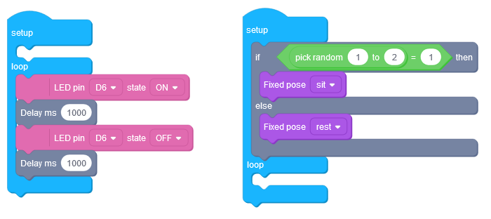
The simplest code for movement includes at least three blocks:
- setup-loop block
- set movement block
- execute movement block
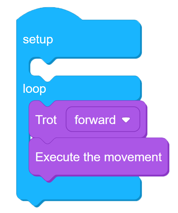 The movement blocks have many lines of codes. Each line represents a set of joint angles which is sent from the Bittle's memory to the motors. The block has the required angle list to complete 1 cycle of walk.
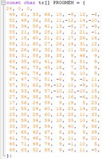
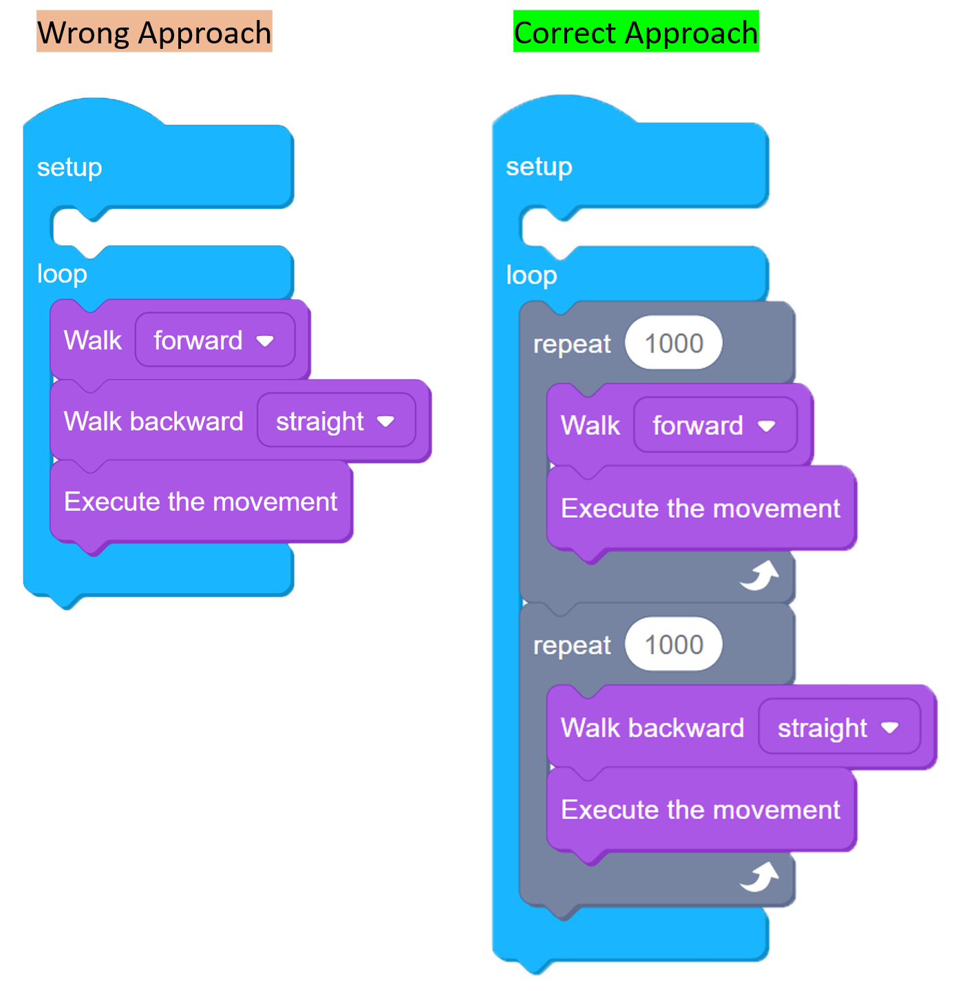
Thus to have a continuous walking movement, you need to repeat the block for some time. In terms of Bittle, this execution differs from other wheel based surface robots. In wheel based surface robots, you only need to set the motors on and off to control the movement. But in case of Bittle or other Legged robots, you need to repeat the movement action for certain amount. An example of moving forward and backward is shown below. In this example, the movements are repeated for 1000 times before changing the action.
13.2.2.1. Variables
To define custom variables, you can add new variables using Variables section in block catalogue. The current version only supports variables of type float.
13.2.2.2. My Blocks
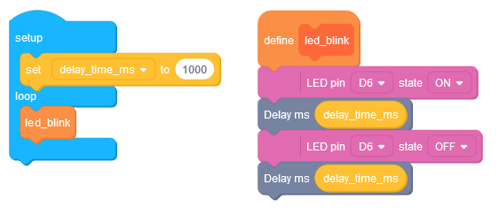
To create custom function block, use the My Blocks section in block catalogue. You can provide 2 type of inputs for the function block; a float value and a boolean value.
13.2.3. IR-Remote Control
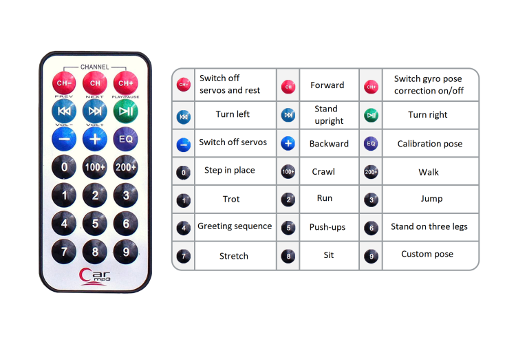
IR Remote can be used in combination to the movement commands to control the robot. The key mapping in reference to Codecraft is provided below:
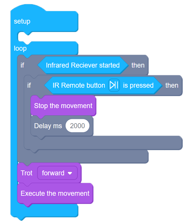
To include IR library in your code, you will need to add a Infrared Receiver started block in your code. This adds the required library and enables the commands related to that library. An example to stop Bittle using IR Remote is shown below. The robot will walk in forward direction until Play/Pause button is pressed on the remote.
You can even use serial monitor to print the raw IR codes of buttons pressed on remote.
13.2.4. Advanced Control
13.2.4.1. Custom Skills
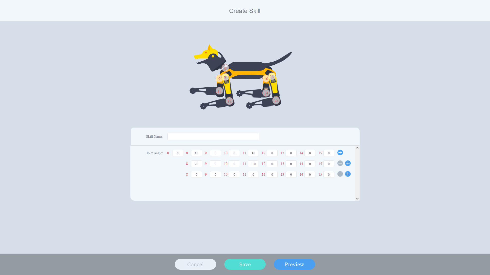
You can create custom skills for your Bittle. To do so, from the Codecraft UI click on Add Extension. Select Create Skill from the Extension Library pop-up. A new catalogue will be added named as Create Skill.
Inside Create Skill, you can set the Joint angles for all the motors on your robot and can create a sequence of different positions to form a complete action just like the walking forward example shown earlier.
13.2.5. Example Block Codes
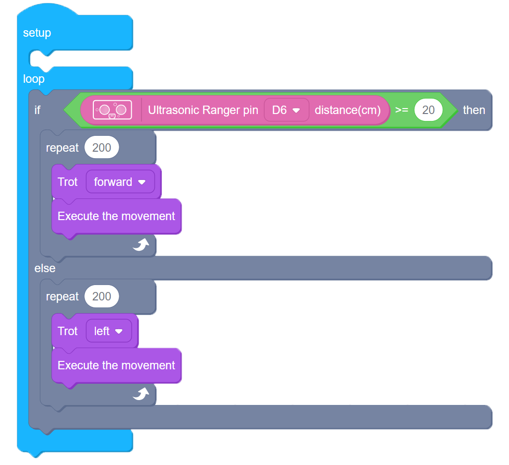
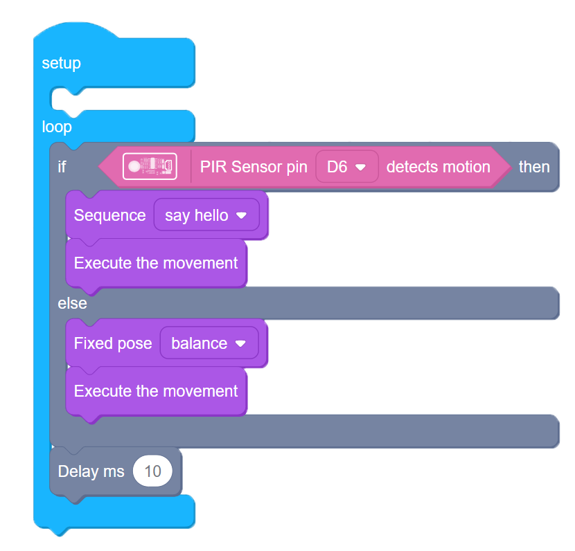
13.2.6. References
- Codecraft website https://ide.tinkergen.com/
- Codecraft tutorials https://www.yuque.com/tinkergen-help-en/codecraft/overview
- Codecraft Bittle tutorials https://www.yuque.com/tinkergen-help-en/bittle_course/preface
14. Problem Solving
14.1. Buzzer Sounds
The robot will keep pausing its movements with beeping sounds when the battery is low. The battery needs to be charged using a a 5V micro-USB cable. Considering safety, the battery won't supply power during charging.
Buzzer sound meaning:

14.2. Download Base Firmware
The OpenCat repository consists of various codes from module test to base firmware.
Warning
After downloading Please DO NOT modify any file until specifically mentioned in the tutorial.
To begin with download,
Copy the link and open it in a browser, the download should start automatically -> https://github.com/PetoiCamp/OpenCat/archive/61fb3efe670c947791739dba86d87118f6021bb8.zip
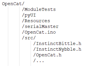
Extract the files and rename the folder to OpenCat. Please check that the files are in following structure /OpenCat/OpenCat.ino
14.3. Install Base Firmware
If in case you are unable to configure your device or its not functioning as intended, try installing the firmware again.
Warning
Before proceeding, please confirm that all wire connections are OK and your code is error free.
If the problem is in your code, the base firmware won't be able to fix it.
Follow the steps below to install base firmware:
- Open Arduino IDE / Platform IO.
- Open OpenCat.ino inside your IDE.
- In the code, select your robot and board version. Uncomment the required lines by removing // and keep the rest of the code as it is.
- Comment out #define MAIN_SKETCH (if you want to configure your board) by adding // in front of the line.
- Set the Board configurations in IDE (Tools-> Board) to Arduino UNO and select the correct COM port.
- Upload the code and open serial monitor.
- Wait until you see Ready on serial monitor.
- If your calibration is successful, Uncomment #define MAIN_SKETCH to make it active. Upload the code again after that.
14.4. Problem Loading Base Firmware
There can be multiple reasons for this, but the most common is incorrect file structure. This file corresponds to the source code downloaded from the link provided. Please consider checking the file structure and comparing it with the structure provided in Download Base Firmware.
14.5. Problem Uploading Program
Please check if the I2C switch on the main board is in correct mode. The I2C switch changes the master of I2C devices (gyro/accelerometer, servo driver, external EEPROM). On default "Arduino", NyBoard uses the onboard ATmega328P as the master chip. On "RPi", NyBoard uses external chips connected through the I2C ports (SDA, SCL) as the master chip.

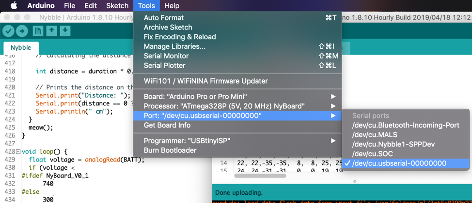
14.6. Problem with Device COM Port
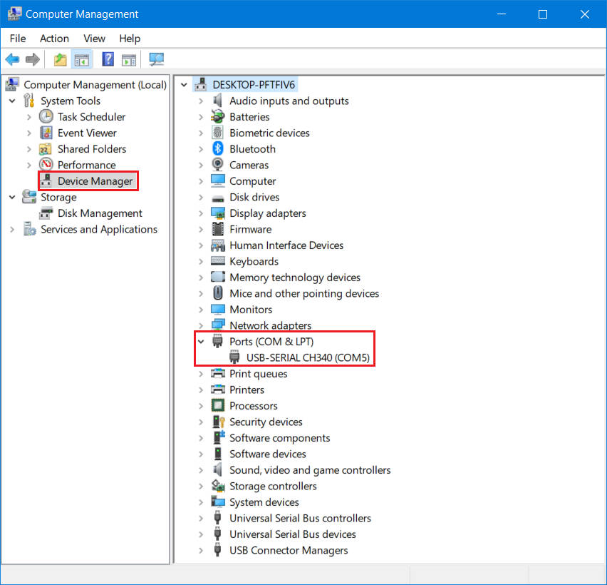
If you cannot find the port for your device on IDE, check the device manager if your device is connected properly and you have the required device driver installed.
The driver required is CH340. You can download it from here -> http://www.wch-ic.com/downloads/CH341SER_ZIP.html
14.7. Problem with Serial Port Permission
If you are using LINUX system and have issues uploading or connecting to COM port, please follow the instructions mentioned here -> https://playground.arduino.cc/Linux/All/#Permission
14.8. Individual Module Test
You can test individual modules of the robot by uploading the codes available under the folder ModuleTests. To do do, open the .ino file from the required test module folder and upload the code by keeping the board setting mentioned earlier.
It is suggested to begin the module test with testBuzzer.ino code.
14.9. Problem with Python Packages
The Terminal is a built-in interface on Mac or Linux machines. The equivalent environment on Windows machines is called the Command-Line Tool (CMD). It's recommended that you install Anaconda to manage your Python environment. It can also provide the Powershell as a Terminal for older Windows machines.
The python scripts work on Python V3. Install pip if not already installed -> https://pip.pypa.io/en/stable/installation/
Install the following packages using pip:
- pyserial
- pillow
pip3 install pyserial pillowTo run the code:
- In the Terminal, use the cd command to navigate to the OpenCat/pyUI/ folder. You can use the Tab key to auto-complete the path name.
- After entering the pyUI/ folder, enter ls and ensure you can see the UI.py and other python source codes listed.
- Enter python3 UI.py.
14.10. Problem Uploading on ESP32 Camera
There are few things to check:
- Correct hardware board selected in Tools menu
- GPIO 0 is set to GND when uploading. Reset once after doing that to enable download mode.
- Hardware is 5V compatible. Try switching to 5V input from FTDI programmer.
- Brownout detector was triggered? Include these header files:
#include "soc/soc.h" //disable brownout problems
#include "soc/rtc_cntl_reg.h"  //disable brownout problems
Include this inside setup()
WRITE_PERI_REG(RTC_CNTL_BROWN_OUT_REG, 0); //disable brownout detectorIf you have other issues, check the following link ( https://randomnerdtutorials.com/esp32-cam-troubleshooting-guide/ )
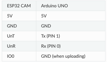
You can also use Arduino UNO to upload code to your ESp32 CAM module.
Connect the following pins:
Steps to use sample code:
- Upload BareMinimun code to your UNO.
- Select the following settings in Tools menu.
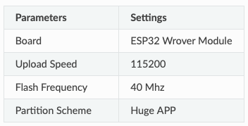
Now you can upload your code to your esp32cam.
