Virtual Commisioning of a Production Line
In this module, virtual commissioning is applied on the Lucas Nülle Industrial Mechatronic System (IMS) assembly line.
Table of Contents
- Learning Outcome
- Task
- Preparation: Station IMS3
- Station IMS3: Practical Assignment
- Preparation: Station IMS4
- Station IMS4: Practical Assignment
- Preparation: Station IMS5
- Station IMS5: Practical Assignment
- Preparation: Station IMS7
- Station IMS7: Practical Assignment
- 11. Summary
-
Troubleshooting
-
12.1 OPC UA Communication Troubleshooting
- Runtime Error: Cannot Connect to This OPC Server
- Green Tick is Missing; Cannot Choose External Variables in External Signal Configuration
- OPC UA Communication Connected but Variables Do Not Get Updated During the Simulation #1
- OPC UA Communication Connected but Variables Do Not Get Updated During the Simulation #2
- Only Some Variables Are Updated Through OPC UA
- 12.2 PLCSIM Advanced V2.0 Troubleshooting
-
12.1 OPC UA Communication Troubleshooting
Learning Outcome
1.1 Introduction
In the context of virtual commissioning, a physics-based model of the Lucas Nülle assembly line should be created and used to verify the PLC control code.

- You will carry out a virtual commissioning application.
- You will get to apply your knowledge of the basics of Siemens NX MCD.
- You will create a physics-based model.
- You will get familiar with the TIA Portal environment.
- You will be able to program Siemens PLCs using FBD, LAD, and SCL programming languages.
- You will be able to simulate 15xx Siemens PLCs.
1.2 Requirements
1.3 What You Need
1.3.1 Software
- Siemens NX version 1872 or newer
- TIA Portal V15 or newer
- PLCSIM Advanced V2.0 or newer
- CAD files of the respective IMS station
1.3.2 Files
CAD files of the IMS stations of the practical assignment as well as for the examples used can be found here.
Task
The goal of the IMS assembly line is to assemble a product that consists of three parts shown in the following figure. Different stations in the assembly line are responsible for mounting different parts of the product or handling the end product.
The end product consists of a top part, a bottom part, and a bolt that connects both parts.

Description
The following sections will handle each IMS station. The task is to build a kinematic model in NX MCD and write a control code in TIA Portal for each station. The control code should be uploaded to a simulated PLC, and an OPC-UA connection should be established between the PLC and the kinematic model.
Preparation: Station IMS3
3.1 Goal
- To get to know the structure and functionality of the IMS3 station.
3.2 Task
The following questions/tasks will help you get familiar with the functionality of the station:
- Identify each of the components highlighted in the following figure and their respective function. Are they sensors or actuators? Would they be defined as inputs or as outputs in a PLC program?

- Describe or outline in a sketch the process of the station.
- Sketch a state machine diagram to describe the functionality of the station.
3.2.1 Siemens NX MCD
- To which elements should a rigid body be assigned in Siemens NX MCD? (Some elements are not highlighted in the figure above.)
- To which elements should a collision body be assigned in Siemens NX MCD? (Some elements are not highlighted in the figure above.)
- To which elements should a joint be assigned in Siemens NX MCD? What type of joints are required to model this station's behavior? Is specifying both attachment object and base object required?
- For which objects should a position control be created? (Hint: Position controls are created to manipulate the position of joints.)
- Which signals should be created inside Siemens NX MCD? What is the function of each signal?
- Which operations should be created? Describe the function of each operation.
3.2.2 PLC Program
- Which inputs and outputs should be defined in the PLC program?
Station IMS3: Practical Assignment
4.1 Goal
- To create a physics-based model of the IMS3 station.
- To implement the state machine of IMS3 in a TIA Portal program.
- To control the physics model with the created state machine program via OPC UA.
4.2 IMS3 Station Functionality
The purpose of the IMS3 station is to mount the base part on the workpiece carrier. The station has a few sensors and actuators, shown in the following figure.


The guiding magazine in the above figures is blinded out; however, the active collision surfaces assigned to it are shown in pink.
4.3 The Virtual Layer - Mechatronics Concept Designer
Physical properties should be assigned to different parts of the IMS3 station. Open the assembly file called ASSEMBLY_IMS3.prt in Siemens NX and navigate to the Mechatronics Concept Designer application.
4.3.1 Base Part and Workpiece Carrier
The base part (the part being mounted) and the workpiece carrier already have rigid body and collision bodies assigned to them. These objects are assigned at the single part's level. To see the objects, double-click on the respective part in the Assembly Navigator window and navigate to the Physics Navigator window.
Definition of collisions: Two objects collide when they get in contact with and exert forces onto each other. Collisions are part of the station's functionality. In the context of the simulation, collisions do not refer to accidents.
Rigid and Collision Bodies Note: When assigning collision bodies to parts, only sides/areas of the part that will undergo collision during the simulation should be chosen. Avoid defining the entire part as a collision body because it increases the complexity of the body and unnecessarily slows down the simulation.
When assigning collision bodies to parts, try to choose simple geometry (box, cylinder, sphere, area, etc.) if complicated geometry (mesh) is not crucial for the physical behavior of the part.

Todo:
- Assign collision bodies to the magazine surfaces that store the parts and along which the parts fall during the separation process. These surfaces keep the parts in place and guide the parts during the separation process.
- Assign other collision bodies to the left and right side areas for the conveyor belt. These areas help guide the carrier along the conveyor belt.
4.3.2 Conveyor Belt
To simulate a conveyor belt, a rectangular surface will be used as a Transport surface. The band itself will be blinded out while the simulation is running.
Todo:
- Assign a Transport surface to the part
200213_TransportflaecheDUMMY. Do this on theEntire_Transport_Bandlevel (double-click onEntire_Transport_Bandfrom the Assembly Navigator to enter that assembly's level).
4.3.3 Mounting Mechanism - Latches
Rigid and Collision Bodies:
A latch prevents the current part from falling and separates parts from the magazine when the mechanism is triggered. Assign a rigid and collision body to the latch. Use the option mesh for the collision body.

Assign physical properties to the latches on the LM9680_Vereinzeln_SE assembly level. Can mesh be avoided? Try using a simplified collision geometry for the parts of the latch that actually collide.
Joint:
The latch should be allowed to rotate around the bolt on which it is mounted.
Todo:
- Assign a hinge joint to the latch. Specify the axis vector and the anchor point around which the latch will rotate. Because the base of the joint (i.e., the rest of the assembly) will not be moving, the base object can be left unassigned. Give the joint a clear name.
Angular Spring Joint:
The latch 'latches' back to its original position through an angular spring joint (also known as a simple torsion spring). Assign an Angular Spring Joint to the latch. Set the spring constant to 20 N.mm/°, damping to 0.1 N.mm.s/°, and relaxed position to 30° away from the up-straight adjustment. The following figure shows the angular position of the latch. In a relaxed position (if there were no cylinder to collide with the latch), the latch would be at a 30° angle to the vertical axis. With the cylinder touching the latch, the 30° is never reached. The resulting new angle (marked in blue) is not relevant to setting the parameters of the Angular Spring Joints.

To check if the given parameters reflect the intended behavior, one can run the simulation and see how the latches will rest. Always run the simulation on the topmost hierarchy level, i.e., in the IMS3 assembly and not in a sub-assembly.
Running the simulation in a sub-assembly might be handy, but it leads to an OPC UA communication bug. Avoid running the simulation unless it's at the topmost assembly level. If OPC UA communication is not working, see the troubleshooting section on how to fix it.
The angular position of the latch will be physically controlled by the latch cylinder. As the cylinder physically pushes onto the latch, it induces the separating motion for the bottom parts magazined in the part tunnel. As the cylinder retracts back, the latch latches back to its original position under the effect of the torsion springs.
4.3.4 Mounting Mechanism - Cylinders (Latch Cylinders and Stopper Cylinder)
A cylinder is used to push the latch and to perform the separation mechanism. When the cylinder is retracted, the latch swings back to its original positions through a torsion spring attached to it.

The torsion spring is not shown in the CAD Model.
Rigid and Collision Bodies:
Todo:
- Assign rigid and collision bodies to the cylinder parts.
When assigning rigid bodies to parts, a few parts can be selected together and defined as one collective rigid body. This should be done if those parts will always undergo the same motion together. In the case of the stopper cylinder, the cylinder itself but also the attached rubber object around it can be selected together.
Joints:
Each cylinder should be constrained in all directions but one. Since every rod will only be either driven out or in, a sliding joint should be assigned to each cylinder.
Todo:
- Assign sliding joints to each cylinder.
As an attachment object, the rods should be chosen. Because the housing of the cylinders will not move during the simulation, the base object can be left unselected. Selecting the housing of the cylinders as the base object is in this case optional.
Make sure to name each of the joints appropriately. For example: Cylinder_SlidingJoint and Stopper_SlidingJoint.
Define a lower limit of 0 and an upper limit of 10. This prevents the physical object from wandering beyond those limits.
Position Control:
To control the position of the object on the sliding joint, position controls have to be assigned to the sliding joint objects.
Todo:
- Create position controls and assign them to each of the sliding objects.
Name the position controls appropriately. For example: Cylinder_PositionControl and Stopper_PositionControl.
Signals:
In order to, in turn, control those position controls through boolean variables from the PLC program later (the goal), one should create signals in MCD and name them appropriately. For example: bStopper_down and bSwings_open.
Only one signal can be responsible for triggering both latches. Therefore, do not create two signals for the two latches, but create one signal to control both of them.
| Signal Name | Signal Function |
|---|---|
| bStopper_down | Sets the stopper's position control position to 5mm |
| bSwing_open | Sets the latch's position control position to 5mm |
Todo:
- Create 2 boolean signals in MCD for the position controls of the cylinders. Be sure to define the signal as an Input, since they are inputs from MCD's perspective.
Do not link the signals to any runtime variables. These signals will trigger operations later.
You can create a symbol table for all of those signals and call it PLCSIM_Advanced. Symbol tables are a good way to arrange and organize signals that are related together. Since these signals will communicate with PLCSIM Advanced, such a name for the symbol table provides clarity.
Operations:
Operations are like if-statements in the MCD simulation. They can be used to trigger something in the simulation if an external (or internal) condition is met.
Todo:
- Create an operation to send the stopper cylinder down. Call it
Stopper_down_operationfor clarity.
Operations can be found in the Sequence Editor menu on the left.
The selected physics object of the operation is the stopper's position control Stopper_PositionControl. The runtime parameter selected is the position, because this is the parameter to be manipulated by the operation. The new value is inserted in the Value column. Under Condition, the condition object selected is the signal bStopper_down. The if-value of the signal should be set to true.

The equivalent in C++ would be:
if(bStopper_down == true) {stopper_sliding_position = 5;}Todo
- Create an additional operation that would set the value of
Stopper_PositionControlto 0 mm ifbStopper_downis false. Call the operationStopper_up_operation. - Create 2 more operations to control the latch cylinder: Use
bSwings_openas the boolean condition-variable for these operations. - Create a boolean signal and use an operation to turn the conveyor belt on and off.
4.3.5 Sensing Mechanism - Entry and Exit Sensors
Collision Sensor
The IMS3 has entry and exit sensors at the start and end of the conveyor belt (see section on IMS3 Station Functionality). These two sensors will be simulated as two small cubes with collision sensor properties.
- Create a new block in mechanical concept under the Home tab. Give the block the dimensions of 10mm x 10mm x 10mm. Under the Assemblies tab, click on Create New to create a new model. Name the model something appropriate, like
end_limit_switch_dummyand click OK. To select the block just created, navigate to Part Navigator on the left-side menu and choose the block that was just created. Now the block is a model and can be seen in the Assembly Navigator. Choose Move Component under the Assemblies tab and move the new block to where the sensor is supposed to be.
When moving an object, clicking on Specify Orientation will enable you to drag on the three axes to move the object.
- Now that the dummy-sensor is in place on the conveyor belt, assign a collision sensor to it. Be sure to call the collision sensor something appropriate, like
End_limit_switch_right.
Signal
For the dummy sensor to send its reading to the PLC, a signal should be created.
- Create a boolean signal and connect it with a runtime parameter. The physics object selected should be the
End_limit_switch_rightobject. Be sure to define the signal as an Output, since it is an output from MCD’s perspective.
It is important to give the signal a clear name. For example: bEnd_limit_switch_right. Where b at the beginning stands for boolean.
The entry sensor is done for now. Later, End_limit_switch_right will be mapped to a PLC signal with the exact same name.
- Go through the same steps again and create a second sensor to detect the carrier’s exit. Call the new sensor signal
bEnd_limit_switch_left.
4.4 The Physical Layer – PLC Program
A program to control the IMS3 station can be found in the downloads. In this module, a PLC will be simulated to control the station.
4.4.1 TIA Portal
The following figure shows a state machine diagram for the IMS3 station. This state machine is implemented in the program.

- Open the program in TIA Portal.
Outputs of the MCD Simulation are inputs of the IMS3 function block, and vice versa. Use the same exact names that are used in the variables in the IMS3 function block in the MCD simulation also. This allows for auto-mapping later.

4.4.2 PLCSIM Advanced
- Start PLCSIM Advanced and start a PLC simulation.
Make sure the PLC simulated has the same name as the PLC in the TIA Portal program.
Make sure PLCSIM Virtual Eth. Adapter is selected.
In TIA Portal, compile your program and upload it to the simulated PLC.
4.5 Controlling the MCD Application using the PLC Program
- Make sure an OPC UA server is configured in the PLC program and connect to it in MCD. When including variables from the PLC program through OPC UA, choose the variables that you need to control the simulated production station.
- In the Signal Mapping window in MCD, click the option Do Auto Mapping. This will automatically map identically-named signals to each other.
- Run the simulation and watch the PLC’s variables in a watch table. The production station should now be controlled through the simulated PLC.
Preparation: Station IMS4
5.1 Goal
- To get to know the structure and functionality of the IMS4 station.
5.2 Task
The following questions/tasks will help you get familiar with the functionality of the station:
- Identify each of the components highlighted in the following figure and their respective function. Are they sensors or actuators? Would they be defined as inputs or as outputs in a PLC program?

- Describe or outline in a sketch the process of the station.
- Sketch a state machine diagram to describe the functionality of the station.
5.2.1 Siemens NX MCD
- To which elements should a rigid body be assigned in Siemens NX MCD? (Some elements are not highlighted in the figure above.)
- To which elements should a collision body be assigned in Siemens NX MCD? (Some elements are not highlighted in the figure above.)
- To which elements should a joint be assigned in Siemens NX MCD? What type of joints are required to model this station's behavior? Is specifying both attachment object and base object required?
- For which objects should a position control be created? (Hint: Position controls are created to manipulate the position of joints.)
- Which signals should be created inside Siemens NX MCD? What is the function of each signal?
- Which operations should be created? Describe the function of each operation.
5.2.2 PLC Program
- Which inputs and outputs should be defined in the PLC program?
Station IMS4: Practical Assignment
6.1 Goal
- To create a physics-based model of the IMS4 station.
- To implement the state machine of IMS4 in a TIA Portal program.
- To control the physics model with the created state machine program via OPC UA.
6.2 IMS4 Station Functionality
The purpose of the IMS4 station is to mount the top part to the already-existing base part. The bottom part arrives on a workpiece carrier being transported on a conveyor belt. To achieve that purpose, the station uses a few sensors and actuators, shown in the following figure.

The IMS4 station has two latch cylinders. One on each side of the top part being separated.


The guiding magazine in the above figures is blinded out; however, the active collision surfaces assigned to it are shown in pink.
6.3 The Virtual Layer - Mechatronics Concept Designer
Physical properties should be assigned to different parts of the IMS4 station. Open the assembly file called IMS4.prt in Siemens NX and navigate to the Mechatronics Concept Designer application.
6.3.1 Top Part, Base Part, and Workpiece Carrier
The base part, top part (the part being mounted), and the workpiece carrier already have rigid body and collision bodies assigned to them. These objects are assigned at the single part's level. To see the objects, double-click on the respective part in the Assembly Navigator window and navigate to the Physics Navigator window.
Definition of collisions: Two objects collide when they get in contact with and exert forces onto each other. Collisions are part of the station's functionality. In the context of the simulation, collisions do not refer to accidents.
Rigid and Collision Bodies Note: When assigning collision bodies to parts, only sides/areas of the part that will undergo collision during the simulation should be chosen. Avoid defining the entire part as a collision body because it increases the complexity of the body and unnecessarily slows down the simulation.
When assigning collision bodies to parts, try to choose simple geometry (box, cylinder, sphere, etc.) if complicated geometry (mesh) is not crucial for the physical behavior of the part.
Todo:
- Assign collision bodies to the magazine surfaces that store the top parts and along which the top parts fall during the separation process. These surfaces keep the top parts in place and guide the top parts during the separation process.
- Assign other collision bodies to the left and right side areas for the conveyor belt. These areas help guide the carrier along the conveyor belt.
6.3.2 Conveyor Belt
To simulate a conveyor belt, a rectangular surface will be used as a Transport surface. The band itself will be blinded out while the simulation is running.
Todo:
- Assign a Transport surface to the part
200213_TransportflaecheDUMMY. Do this on theEntire_Transport_Bandlevel.
6.3.3 Mounting Mechanism - Latches
Rigid and Collision Bodies:
The latches on both sides are what hold the parts from falling. They also separate the parts in two steps. Because they will collide with the top parts, rigid and collision bodies should be assigned to them. Because the latches' shape is crucial to their functionality, the option mesh should be chosen when assigning collision bodies to both latches.

Assign physical properties to the latches on the LM9681_Montage assembly level. Can mesh be avoided? Try using a simplified collision geometry for the parts of the latch that actually collide.
Joints:
Both latches should be allowed to rotate along the bolts on which they are mounted.
Todo:
- Assign hinge joints to both latches. Specify the axis vector and the anchor point around which the latches will rotate. Because the base of the joint will not be moving, the base object can be left unassigned. Give the joints a clear name.
Angular Spring Joints:
Each latch 'latches' back to its original position through an angular spring joint (also known as a simple torsion spring). Assign an Angular Spring Joint to each of the latches. Set the spring constant to 20 N.mm/°, damping to 0.1 N.mm.s/°, and relaxed position to 30° away from the up-straight adjustment. The following figure shows the angular position of one latch. In a relaxed position (if there were no cylinder to collide with the latch), the latch would be at a 30° angle to the vertical axis. With the cylinder touching the latch, the 30° is never reached. The resulting new angle (marked in blue) is not relevant to setting the parameters of the Angular Spring Joints.
To check if the given parameters reflect the intended behavior, one can run the simulation and see how the latches will rest. Always run the simulation on the topmost hierarchy level, i.e., in the IMS4 assembly and not in a sub-assembly.
Running the simulation in a sub-assembly might be handy, but it leads to an OPC UA communication bug. Avoid running the simulation unless it's at the topmost assembly level. If OPC UA communication is not working, see the troubleshooting section on how to fix it.
The angular position of the latches will be physically controlled by the latch cylinders. As the cylinders physically push onto the latches, they induce the separating motion for the top parts magazined in the part tunnel. As the cylinders retract back, the latches latch back to their original position under the effect of their torsion springs.
6.3.4 Mounting Mechanism - Cylinders (Latch Cylinders and Stopper Cylinder)
Two cylinders are used to move the latches and create the part-separating motion. When the cylinders are retracted, the latches swing back to their original positions through a torsion spring attached to them (not shown in the CAD model).

Rigid and Collision Bodies:
Todo:
- Assign rigid and collision bodies to the cylinder parts.
When assigning rigid bodies to parts, a few parts can be selected together and defined as one collective rigid body. This should be done if those parts will always undergo the same motion together. In the case of the stopper cylinder, the cylinder itself but also the attached gummy object around it can be selected together.
Joints:
Each cylinder should be constrained in all directions but one. Since every cylinder will only be either driven out or in, a sliding joint should be assigned to each cylinder.
Todo:
- Assign sliding joints to each cylinder.
As an attachment object, the cylinder itself should be chosen. Because the housing of the cylinders will not move during the simulation, the base object can be left unselected. Selecting the housing of the cylinders as the base object is in this case optional.
Make sure to name each of the joints appropriately. For example: Latch_1_SlidingJoint, Latch_2_SlidingJoint, and Stopper_SlidingJoint.
Define a lower limit of 0 and an upper limit of 10. This prevents the physical object from wandering beyond those limits.
Position Control:
To control the position of the object on the sliding joint, position controls have to be assigned to the sliding joint objects.
Todo:
- Create position controls and assign them to each of the 3 sliding objects.
Name the position controls appropriately. For example: Latch_1_PositionControl, Latch_2_PositionControl, and Stopper_PositionControl.
Signals:
In order to, in turn, control those position controls through boolean variables from the PLC program later (the goal), one should create signals in MCD and name them appropriately. For example: bStopper_down and bSwings_open.
Only one signal can be responsible for triggering both latches. Therefore, do not create two signals for the two latches, but create one signal to control both of them.

Todo:
- Create 2 boolean signals in MCD for the position controls of the cylinders. Be sure to define the signal as an Input, since they are inputs from MCD's perspective.
Do not link the signals to any runtime variables. These signals will trigger operations later.
You can create a symbol table for all of those signals and call it PLCSIM_Advanced. Symbol tables are a good way to arrange and organize signals that are related together. Since these signals will communicate with PLCSIM Advanced, such a name for the symbol table provides clarity.
Operations:
Operations are like if-statements in the MCD simulation. They can be used to trigger something in the simulation if an external (or internal) condition is met.
Todo:
- Create an operation to send the stopper cylinder down. Call it
Stopper_down_operationfor clarity.
Operations can be found in the Sequence Editor menu on the left.
The selected physics object of the operation is the stopper's position control Stopper_PositionControl. The runtime parameter selected is the position, because this is the parameter to be manipulated by the operation. The new value is inserted in the Value column. Under Condition, the condition object selected is the signal bStopper_down. The if-value of the signal should be set to true.
The equivalent in C++ would be:
if(bStopper_down == true) {stopper_sliding_position = 5;}Todo
- Create an additional operation that would set the value of
Stopper_PositionControlto 0 mm ifbStopper_downis false. Call the operationStopper_up_operation. - Create 4 more operations to control both latch-cylinders: Two operations to drive the cylinders out and two operations to drive the cylinders in. Use
bSwings_openas the boolean condition-variable for these operations. - Create a boolean signal and use an operation to turn the conveyor belt on and off.
6.3.5 Sensing Mechanism - Entry and Exit Sensors
Collision Sensor
The IMS4 has entry and exit sensors at the start and end of the conveyor belt (see section on IMS4 Station Functionality). These two sensors will be simulated as two small cubes with collision sensor properties.
- Create a new block in mechanical concept under the Home tab. Give the block the dimensions of 10mm x 10mm x 10mm. Under the Assemblies tab, click on Create New to create a new model. Name the model something appropriate, like
end_limit_switch_dummyand click OK. To select the block just created, navigate to Part Navigator on the left-side menu and choose the block that was just created. Now the block is a model and can be seen in the Assembly Navigator. Choose Move Component under the Assemblies tab and move the new block to where the sensor is supposed to be.
When moving an object, clicking on Specify Orientation will enable you to drag on the three axes to move the object.
- Now that the dummy-sensor is in place on the conveyor belt, assign a collision sensor to it. Be sure to call the collision sensor something appropriate, like
End_limit_switch_right.
Signal
For the dummy sensor to send its reading to the PLC, a signal should be created.
- Create a boolean signal and connect it with a runtime parameter. The physics object selected should be the
End_limit_switch_rightobject. Be sure to define the signal as an Output, since it is an output from MCD's perspective.
It is important to give the signal a clear name. For example: bEnd_limit_switch_right. Where b at the beginning stands for boolean.
The entry sensor is done for now. Later, End_limit_switch_right will be mapped to a PLC signal with the exact same name.
- Go through the same steps again and create a second sensor to detect the carrier's exit. Call the new sensor signal
bEnd_limit_switch_left.
6.4 The Physical Layer – PLC Program
A program to control the IMS4 station can be found in the downloads. In this module, a PLC will be simulated to control the station.
6.4.1 TIA Portal
The following figure shows a state machine diagram for the IMS4 station. This state machine is implemented in the program.

- Open the program in TIA Portal.
Outputs of the MCD Simulation are inputs of the IMS4 function block, and vice versa. Use the same exact names that are used in the variables in the IMS4 function block in the MCD simulation also. This allows for auto-mapping later.

6.4.2 PLCSIM Advanced
- Start PLCSIM Advanced and start a PLC simulation.
Make sure the PLC simulated has the same name as the PLC in the TIA Portal program.
Make sure PLCSIM Virtual Eth. Adapter is selected.
In TIA Portal, compile your program and upload it to the simulated PLC.
6.5 Controlling the MCD Application using the PLC Program
- Make sure an OPC UA server is configured in the PLC program and connect to it in MCD. When including variables from the PLC program through OPC UA, choose the variables that you need to control the simulated production station.
- In the Signal Mapping window in MCD, click the option Do Auto Mapping. This will automatically map identically-named signals to each other.
- Run the simulation and watch the PLC's variables in a watch table. The production station should now be controlled through the simulated PLC.
Preparation: Station IMS5
7.1 Goal
- To get to know the structure and functionality of the IMS5 station.
7.2 Task
The following questions/tasks will help you get familiar with the functionality of the station:
- Identify each of the components highlighted in the following figure and their respective function. Are they sensors or actuators? Would they be defined as inputs or as outputs in a PLC program?

- Describe or outline in a sketch the process of the station.
- Sketch a state machine diagram to describe the functionality of the station.
7.2.1 Siemens NX MCD
- To which elements should a rigid body be assigned in Siemens NX MCD? (Some elements are not highlighted in the figure above.)
- To which elements should a collision body be assigned in Siemens NX MCD? (Some elements are not highlighted in the figure above.)
- To which elements should a joint be assigned in Siemens NX MCD? What type of joints are required to model this station's behavior? Is specifying both attachment object and base object required?
- For which objects should a position control be created? (Hint: Position controls are created to manipulate the position of joints.)
- Which signals should be created inside Siemens NX MCD? What is the function of each signal?
- Which operations should be created? Describe the function of each operation.
7.2.2 PLC Program
- Which inputs and outputs should be defined in the PLC program?
Station IMS5: Practical Assignment
8.1 Goal
- To create a physics-based model of the IMS5 station.
- To implement the state machine of IMS5 in a TIA Portal program.
- To control the physics model with the created state machine program via OPC UA.
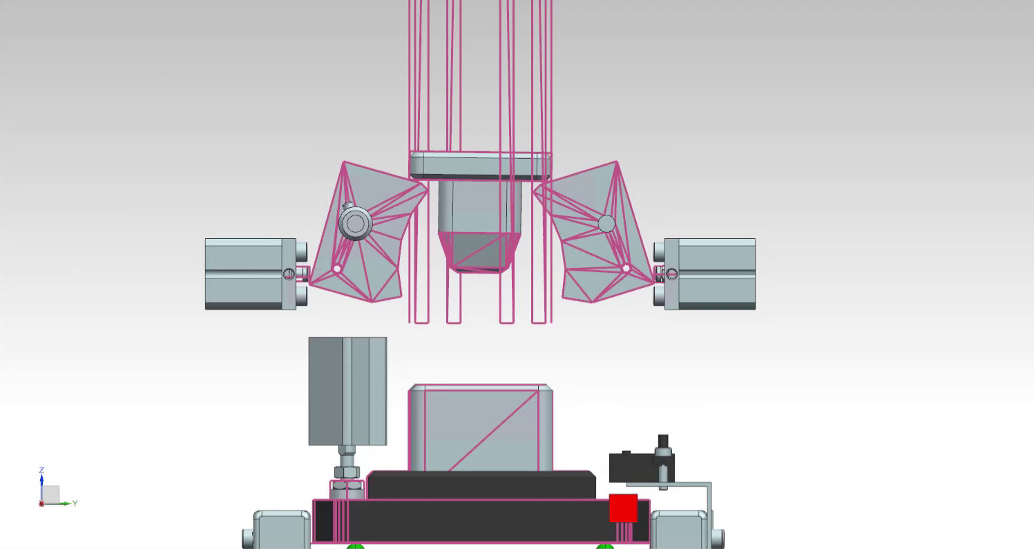
8.2 IMS5 Station Functionality
The purpose of the IMS5 station is to insert a bolt that connects the top part and the bottom part together. Both parts arrive on the workpiece carrier that is transported on a conveyor belt. The station uses a few sensors and actuators shown in the following figure.

A left end limit switch exists on the left end of the conveyor belt.

The guiding magazine in the above animation is blinded out; however, the active collision surfaces assigned to it are shown in pink.
8.3 The Virtual Layer - Mechatronics Concept Designer
Physical properties should be assigned to different parts of the IMS5 station. Open the assembly file called ASSEMBLY_IMS5.prt in Siemens NX and navigate to the Mechatronics Concept Designer application.
8.3.1 Top Part, Base Part, Bolt, and Workpiece Carrier
The base part, top part, bolt (the part being mounted), and the workpiece carrier already have rigid body and collision bodies assigned to them. These objects are assigned at the single part's level. To see the objects, double-click on the respective part in the Assembly Navigator window and navigate to the Physics Navigator window.
The definition of collisions: Two objects collide when they get in contact with and exert forces onto each other. Collisions are part of the station's functionality. In the context of the simulation, collisions do not refer to accidents.
Rigid and Collision Bodies Note: When assigning collision bodies to parts, only sides/areas of the part that will undergo collision during the simulation should be chosen. Avoid defining the entire part as a collision body because it increases the complexity of the body and unnecessarily slows down the simulation.
When assigning collision bodies to parts, try to choose simple geometry (box, cylinder, sphere, etc.) if complicated geometry (mesh) is not crucial for the physical behavior of the part.
Todo:
- Assign collision bodies to the magazine surfaces that store the bolts and along which the bolts fall during the separation process. These surfaces keep the bolts in place and guide the bolts during the separation process.
- Assign other collision bodies to the left and right side areas for the conveyor belt. These areas help guide the carrier along the conveyor belt.
8.3.2 Conveyor Belt
To simulate a conveyor belt, a rectangular surface will be used as a transport surface. The band itself will be blinded out while the simulation is running.
Todo:
- Assign a transport surface to the part
200213_TransportflaecheDUMMY. Do that on theEntire_Transport_Bandlevel.
8.3.3 Mounting Mechanism - Cylinders (Mounting Cylinder and Stopper Cylinder)
A pneumatic cylinder is used to push the bolt into the other pieces. Another cylinder is used as a stopper for the workpiece carrier.
Rigid and Collision Bodies:
Todo:
- Assign rigid and collision bodies to the appropriate cylinder parts.
When assigning rigid bodies to parts, a few parts can be selected together and defined as one collective rigid body. This should be done if those parts will always undergo the same motion together. In the case of the stopper cylinder, the cylinder itself but also the attached gummy object around it can be selected together.
Joints:
Each cylinder rod should be constrained in all directions but one. Since every cylinder will only be either driven out or in, a sliding joint should be assigned to each cylinder rod.
Todo:
- Assign sliding joints to each cylinder.
As an attachment object, the cylinder's rod should be chosen. Because the housing of the cylinders will not move during the simulation, the base object can be left unselected. Selecting the housing of the cylinders as the base object is in this case optional.
Make sure to name each of the joints appropriately. For example: Cylinder_SlidingJoint and Stopper_SlidingJoint.
Define a lower limit of 0 and an upper limit of 10. This prevents the physical object from wandering beyond those limits.
Position Control:
To control the position of the object on the sliding joint, position controls have to be assigned to the sliding joint objects.
Todo:
- Create position controls and assign them to each of the sliding objects.
Note: Name the position controls appropriately. For example: Cylinder_PositionControl and Stopper_PositionControl.
Signals:
In order to, in turn, control those position controls through boolean variables from the PLC program later (the goal), one should create signals in MCD and name them appropriately. For example: bStopper_down and bCylinder_out.

Todo:
- Create 2 boolean signals in MCD for the position controls of the cylinders. Be sure to define the signals as Inputs, since they are inputs from MCD's perspective.
Do not link the signals to any runtime variables. These signals will trigger operations later.
You can create a symbol table for all of those signals and call it PLCSIM_Advanced. Symbol tables are a good way to arrange and organize signals that are related together. Since these signals will communicate with PLCSIM Advanced, such a name for the symbol table provides clarity.
Operations:
Operations are like if-statements in the MCD simulation. They can be used to trigger something in the simulation if an external (or internal) condition is met.
Todo:
- Create an operation to send the stopper cylinder down. Call it
Stopper_down_operationfor clarity.
Operations can be found in the Sequence Editor menu on the left.
The selected physics object of the operation is the stopper's position control Stopper_PositionControl. The runtime parameter selected is the position; this is the parameter to be manipulated by the operation. The new value is inserted in the Value column. Under Condition, the condition object selected is the signal bStopper_down. The if-value of the signal should be set to true.
The equivalent in C++ would be:
if(bStopper_down == true) {stopper_sliding_position = 5;}Todo
- Create an additional operation that would set the value of
Stopper_PositionControlto 0 mm ifbStopper_downis false. Call the operationStopper_up_operation. - Create two more operations to control the mounting cylinder: One operation to drive the cylinder out and one operation to drive the cylinder in. Use
bCylinder_outas the boolean condition-variable for these operations. - Create a boolean signal and use an operation to turn the conveyor belt on and off.
8.3.4 Sensing Mechanism - Entry and Exit Sensors
Collision Sensor
The IMS5 has entry and exit sensors at the start and end of the conveyor belt (see section on IMS5 Station Functionality). These two sensors will be simulated as two small cubes with collision sensor properties.
- Create a new block in mechanical concept under the Home tab. Give the block the dimensions of 10mm x 10mm x 10mm. Under the Assemblies tab, click on Create New to create a new model. Name the model something appropriate, like
end_limit_switch_dummyand click OK. To select the block just created, navigate to Part Navigator on the left-side menu and choose the block that was just created. Now the block is a model and can be seen in the Assembly Navigator. Choose Move Component under the Assemblies tab and move the new block to where the sensor is supposed to be.
When moving an object, clicking on Specify Orientation will enable you to drag on the three axes to move the object.
- Now that the dummy-sensor is in place on the conveyor belt, assign a collision sensor to it. Be sure to call the collision sensor something appropriate, like
End_limit_switch_right.
Signal
For the dummy sensor to send its reading to the PLC, a signal should be created.
- Create a boolean signal and connect it with a runtime parameter. The physics object selected should be the
End_limit_switch_rightobject. Be sure to define the signal as an Output, since it is an output from MCD's perspective.
It is important to give the signal a clear name. For example: bEnd_limit_switch_right. Where b at the beginning stands for boolean.
The entry sensor is done for now. Later, End_limit_switch_right will be mapped to a PLC signal with the exact same name.
- Go through the same steps again and create a second sensor to detect the carrier's exit. Call the new sensor signal
bEnd_limit_switch_left.
8.4 The Physical Layer – PLC Program
A program to control the IMS5 station can be found in the downloads. In this module, a PLC will be simulated to control the station.
8.4.1 TIA Portal
The following figure shows a state machine diagram for the IMS5 station. This state machine is implemented in the program.

- Open the program in TIA Portal.
Outputs of the MCD Simulation are inputs of the IMS5 function block, and vice versa. Use the same exact names that are used in the variables in the IMS5 function block in the MCD simulation also. This allows for auto-mapping later.

8.4.2 PLCSIM Advanced
- Start PLCSIM Advanced and start a PLC simulation.
Make sure the PLC simulated has the same name as the PLC in the TIA Portal program.
Make sure PLCSIM Virtual Eth. Adapter is selected.
In TIA Portal, compile your program and upload it to the simulated PLC.
8.5 Controlling the MCD Application using the PLC Program
- Make sure an OPC UA server is configured in the PLC program and connect to it in MCD. When including variables from the PLC program through OPC UA, choose the variables that you need to control the simulated production station.
- In the Signal Mapping window in MCD, click the option Do Auto Mapping. This will automatically map identically-named signals to each other.
- Run the simulation and watch the PLC's variables in a watch table. The production station should now be controlled through the simulated PLC.
Preparation: Station IMS7
9.1 Goal
- To get to know the structure and functionality of the IMS7 station.
9.2 Task
The following questions/tasks will help you get familiar with the functionality of the station:
- Identify each of the components highlighted in the following figure and their respective function. Are they sensors or actuators? Would they be defined as inputs or as outputs in a PLC program?

- Describe or outline in a sketch the process of the station.
- Sketch a state machine diagram to describe the functionality of the station.
9.2.1 Siemens NX MCD
- To which elements should a rigid body be assigned in Siemens NX MCD? (Some elements are not highlighted in the figure above.)
- To which elements should a collision body be assigned in Siemens NX MCD? (Some elements are not highlighted in the figure above.)
- To which elements should a joint be assigned in Siemens NX MCD? What type of joints are required to model this station's behavior? Is specifying both attachment object and base object required?
- For which objects should a position control be created? (Hint: Position controls are created to manipulate the position of joints.)
- Which signals should be created inside Siemens NX MCD? What is the function of each signal?
- Which operations should be created? Describe the function of each operation.
9.2.2 PLC Program
- Which inputs and outputs should be defined in the PLC program?
Station IMS7: Practical Assignment
10.1 Goal
- To create a physics-based model of the IMS7 station.
- To implement the state machine of IMS7 in a TIA Portal program.
- To control the physics model with the created state machine program via OPC UA.
10.2 IMS7 Station Functionality
The purpose of the IMS7 station is to pick-and-place the end-product from the assembly line onto an outside platform. It does so by using a vacuum gripper and a rotating arm to lift the end-product and re-place it on the platform. The station has a few sensors and actuators, shown in the following figure.


10.3 The Virtual Layer - Mechatronics Concept Designer
Physical properties should be assigned to different parts of the IMS7 station. Open the assembly file called ASSEMBLY_IMS7.prt in Siemens NX and navigate to the Mechatronics Concept Designer application.
10.3.1 Top Part, Base Part, Bolt, and Workpiece Carrier
Assign rigid bodies to all parts that are going to move/collide during the simulation of the station. All parts that will not move/collide during the simulation should be ignored.
Rigid and Collision Bodies
Todo:
- Assign rigid and collision bodies to the top part, the base part, bolt, and the carrier.
When assigning rigid bodies to parts, a few parts can be selected together and defined as one collective rigid body. This should be done if those parts will always undergo the same motion together.
When assigning collision bodies to parts, only sides/areas of the part that will undergo collision during the simulation should be chosen. Avoid defining the entire part as a collision body because it increases the complexity of the body and unnecessarily slows down the simulation.
When assigning collision bodies to parts, try to choose simple geometry (box, cylinder, sphere, etc.) if complicated geometry (mesh) is not crucial for the physical behavior of the part.
Todo:
- Assign a collision body to the platform that receives the end-product.
10.3.2 Conveyor Belt
To simulate a conveyor belt, a rectangular surface will be used as a Transport surface. The band itself will be blinded out while the simulation is running.
Todo:
- Assign a Transport surface to the part
200213_TransportflaecheDUMMY. Do that on theEntire_Transport_Bandlevel.
10.3.3 Pick and Place Mechanism
Rigid and Collision Bodies:
The entire arm rotates to bring the end-product to the specified platform. Because all components of the arm undergo the same motion together at all times during the simulation, they should be defined as a unified rigid body.

Because the cylinder's rod will undergo a different motion than the rest of the arm, it should not be included in the same rigid body definition. The cylinder's rod should be defined as its own rigid body.

Todo:
- Assign a rigid body and a collision body to the cylinder's rod and to the stopper's rod.
Joints:
Todo:
- Assign a sliding joint to both the cylinder's rod and the stopper's rod and enter appropriate limits.
Does the base object have to be specified in both cylinder's cases? Why or why not?
Special Joint Case: Vacuum Gripper
A fixed joint should be created between the gripper and the top part being picked up. Because those two parts belong to different sub-assemblies, only the base of the fixed joint (the gripper) should be given when creating the fixed joint. The attachment of the fixed joint (the product) should be assigned to the fixed joint later during the simulation using an operation. The top part is connected to the bottom part through a magnetic contact in addition to the bolt. The magnetic contact will also be simulated using a fixed joint.
Todo:
- Create a fixed joint between the gripper and the top part. Create another fixed joint between the top part and the base part. At first, give in only the base objects (the gripper for the first fixed joint and the top part for the second fixed joint respectively). Manipulate those fixed joints by adding their attachment objects later in the simulation when the gripper is supposed to lift the product using an operation (see section on operations).
Todo:
- Optional task: Is there a way to let the product fall (switch off the fixed joint) if the product's weight exceeds a certain limit? Describe the approach briefly.
Position Controls:
Todo:
- Assign position control objects to each of the joints.
Signals:
Todo:
- Assign signals to each of the position control objects.
Operations:
Operations are like if-statements in the MCD simulation. They can be used to trigger something in the simulation if an external (or internal) condition is met.
Operations can be found in the Sequence Editor menu on the left.
Todo:
- Create an operation to send the stopper cylinder down. Call it
Stopper_down_operationfor clarity.
The selected physics object of the operation is the stopper's position control. The runtime parameter selected is the position, because this is the parameter to be manipulated by the operation. The new value is inserted in the Value column. Under Condition, the condition object selected is the signal that was created to control the stopper.
The equivalent in C++ would be:
if(bStopper_down == true) {stopper_sliding_position = 5;}Todo
-
Create operations to rotate the arm, drive the pneumatic cylinder down, and turn on the gripper (turn on the Stick when Collision property of the gripper's collision body).
-
Determine the position control values by measuring the length of the rod and taking the start position into consideration.
10.3.4 Sensing Mechanism - Entry and Exit Sensors
Collision Sensor
The IMS7 has entry and exit sensors at the start and end of the conveyor belt (see section on IMS7 Station Functionality). These two sensors will be simulated as two small cubes with collision sensor properties.
- Create a new block in mechanical concept under the Home tab. Give the block the dimensions of 10mm x 10mm x 10mm. Under the Assemblies tab, click on Create New to create a new model. Name the model something appropriate, like
end_limit_switch_dummyand click OK. To select the block just created, navigate to Part Navigator on the left-side menu and choose the block that was just created. Now the block is a model and can be seen in the Assembly Navigator. Choose Move Component under the Assemblies tab and move the new block to where the sensor is supposed to be.
When moving an object, clicking on Specify Orientation will enable you to drag on the three axes to move the object.
- Now that the dummy-sensor is in place on the conveyor belt, assign a collision sensor to it. Be sure to call the collision sensor something appropriate, like
End_limit_switch_right.
Signal
For the dummy sensor to send its reading to the PLC, a signal should be created.
- Create a boolean signal and connect it with a runtime parameter. The physics object selected should be the
End_limit_switch_rightobject. Be sure to define the signal as an Output, since it is an output from MCD's perspective.
It is important to give the signal a clear name. For example: bEnd_limit_switch_right. Where b at the beginning stands for boolean.
The entry sensor is done for now. Later, End_limit_switch_right will be mapped to a PLC signal with the exact same name.
- Go through the same steps again and create a second sensor to detect the carrier's exit. Call the new sensor signal
bEnd_limit_switch_left.
10.4 The Physical Layer – PLC Program
A program to control the IMS7 station can be found in the downloads. In this module, a PLC will be simulated to control the station.
10.4.1 TIA Portal
The following figure shows a state machine diagram for the IMS7 station. This state machine is implemented in the program.

- Open the program in TIA Portal.
Outputs of the MCD Simulation are inputs of the IMS7 function block, and vice versa. Use the same exact names that are used in the variables in the IMS7 function block in the MCD simulation also. This allows for auto-mapping later.

10.4.2 PLCSIM Advanced
- Start PLCSIM Advanced and start a PLC simulation.
Make sure the PLC simulated has the same name as the PLC in the TIA Portal program.
Make sure PLCSIM Virtual Eth. Adapter is selected.
In TIA Portal, compile your program and upload it to the simulated PLC.
10.5 Controlling the MCD Application using the PLC Program
-
Make sure an OPC UA server is configured in the PLC program and connect to it in MCD. When including variables from the PLC program through OPC UA, choose the variables that you need to control the simulated production station.
-
In the Signal Mapping window in MCD, click the option Do Auto Mapping. This will automatically map identically-named signals to each other.
-
Run the simulation and watch the PLC's variables in a watch table. The production station should now be controlled through the simulated PLC.
11. Summary
The virtual commissioning of an entire production line is a process that takes effort to achieve but reduces the overall project time through early verification of the control code.
After simulating each station and testing the individual code, the next step would be to combine all stations in one whole simulation of the entire production line. Likewise, the individual codes should also be combine and the entire setup should be tested for further bugs. Bringing us a step closer to a more confident real commissioning with the real hardware.
Troubleshooting
12.1 OPC UA Communication Troubleshooting
Runtime Error: Cannot Connect to This OPC Server
If upon starting the simulation the above error shows up, navigate to External Signal Configuration in the Automation tab. The connection status of the OPC Server has to be 'connected'. If the status is 'connected', click OK and try running the simulation again. If the status is 'unknown', click on Refresh Server Status. This may change the status back to 'connected' and the simulation will then run.
Green Tick is Missing; Cannot Choose External Variables in External Signal Configuration
If this is the case, close all open assemblies and restart Siemens NX.
OPC UA Communication Connected but Variables Do Not Get Updated During the Simulation #1
If the OPC UA communication is successful and mapping is done correctly, but the variables do not get updated through OPC UA in either direction (i.e., both inputs and outputs do not respond), then a certain part or sub-assembly is causing this problem. The solution is to start rebuilding the current main assembly in a new file and adding each part one by one, testing the OPC UA connection after adding each part. This way, you will be able to spot the part and/or assembly that is causing the communication issue.
If the cause of the issue is a sub-assembly, create a new sub-assembly with a different name and import all parts of the old sub-assembly into it. Use the new assembly instead of the old one. This should allow the communication to function.
If the cause of the problem is a part, reconstruct the part in a new file and use the new part (copying the old part into a new file does not resolve the problem).
OPC UA Communication Connected but Variables Do Not Get Updated During the Simulation #2
If the OPC UA communication was running perfectly but all of a sudden the variables stop responding, this may be caused by running a simulation only on a sub-assembly or part level. Undoing the past 3 steps and reselecting the main assembly then running the simulation will undo this problem.
Siemens NX MCD offers the possibility to run simulations on the sub-assembly or part level. This is helpful to see how only one part will be simulated without simulating the entire assembly. However, it is recommended to run the simulation only on the main assembly level because of this OPC UA communication bug.
Only Some Variables Are Updated Through OPC UA
This issue occurs when communicating with a PLC program over OPC UA.
In case the OPC UA communication seems to function with only some variables and with other variables it seems to be down, make sure that the variables being transferred over OPC UA are declared in a function block in the PLC program and not mapped directly to a PLC I/O module.
12.2 PLCSIM Advanced V2.0 Troubleshooting
PLC Instance Cannot Be Started: License Could Not Be Found
If the simulation instance of a PLC does not run, open PLCSIM Advanced as an administrator and try again.