FluidSimLogiGateTech
Table of Contents
Lab Session 2 - Logic Elements:
📌 What's the goal of this lab session?
After building control circuits using relay technology, the next step is to transition into the world of digital control. This will be done using logic elements connected within a virtual controller in FluidSim. This lab session serves as a bridge to prepare you for the next stage: programming PLCs.
Preparation
The following section contains an introduction to the logic elements to create logic circuits. Please carefully execute the todos as this knowledge is required for the practical session. This part is for the 2nd practical session.
Logic circuits are fundamental building blocks in digital electronics, enabling complex decision-making processes in electronic devices. Before the advent of logic circuits, relay technologies were used for controlling electrical operations. Relays, which are electromechanical switches, could perform basic logic operations but were bulky, slow, and prone to wear and tear due to mechanical movement.
With the development of semiconductor technology, logic circuits using AND and OR gates emerged. These gates, composed of transistors, allowed for faster, more reliable, and smaller electronic devices than relays. AND gates output a high signal only if all their inputs are high, while OR gates output a high signal if at least one of their inputs is high. These basic gates can be combined to create more complex circuits capable of performing intricate tasks.
Logic circuits paved the way for programmable logic controllers (PLCs) and microcontrollers. PLCs are robust devices used in industrial automation to control machinery and processes. They can be programmed to perform a variety of tasks and are essential in manufacturing and production lines. Microcontrollers, on the other hand, are compact integrated circuits that serve as the brains of many modern electronic devices, from household appliances to sophisticated robotics. They execute pre-programmed instructions to control the functions of these devices efficiently.
In summary, logic circuits marked a significant technological advancement from relay-based systems and laid the groundwork for the sophisticated digital control systems we rely on today. (Source: ChatGPT)
Why do we need logic circuits?
Because they make it possible to manipulate and analyze binary data, logic gates are crucial parts of digital electronics. Complex digital circuits may be built by combining several logic gates to carry out tasks including simple calculations, complicated computations, memory storage, decision-making, and more. They serve as the cornerstone of digital systems, which encompasses almost all contemporary electronic gadgets as well as computers, calculators, and smartphones. (Source: IBE Electronics)
You can find even essential information on logic gates here and here. If you are not familiar with logic gates. Please visit these links!!!
Logic in FluidSIM
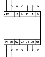
FluidSIM has a special block for logic circuits. This block has several inputs and outputs and works as a "BlackBox"
You can insert the logic block to your drawing. To edit it's content, double click on it. A seperate window will open, here you can create your logic using the gates.
In simulation mode, you can manually set the inputs to high, by pressing onto them.
This block only contains logic. It is the "predecessor" to the PLC, that we will code in the next lab sessions. Motors, and other high enery devices will be controlled via relays, that are set with the outputs of the logic elements.
Logic circuits
For this lab session, basic comprehension of logic elements is required. Please make yourself familiar with logic elements. For example here wikipedia.org
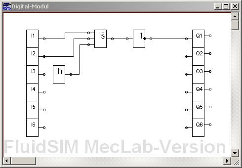
In FluidSIM®, logic modules can be used to control interactions, e.g. by relays. The digital module can be found in FluidSIM® in the components under the Digital Technology category. Place it in a new circuit; double-click on the placed digital module to open a window in which you can edit the functions of the digital module.
Use this file as an answering sheet: File.pdf
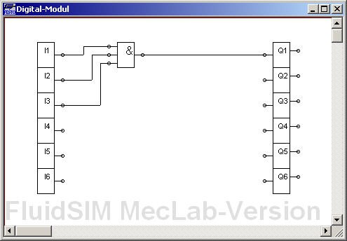
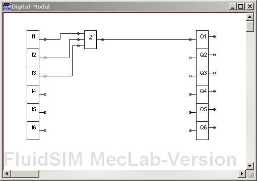
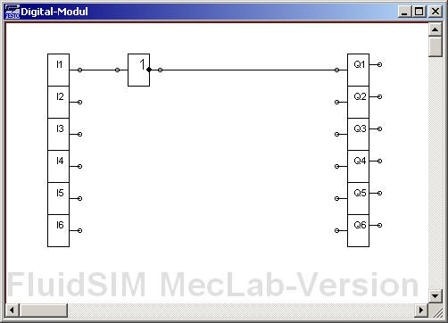
Create and fill a truth table for the inputs and the output Q1, for the given logic circuits. In the practical session, transfer the following logic circuits into FluidSIM® and examine the behavior of the circuits by starting the simulation and setting the input channels I1 to I3 to the HIGH state by clicking on them.
Flip-Flops
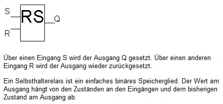
Holding elements - or flip-flops - are storing elements. The RS flip-flop is the simplest flip-flop. It has a set input and a reset input. Thus the name RS-FlipFlop.
Flags
Often the results of logic operations depend on previous results. These results must be stored temporarily so that they can be used in the next cycle. Flags are used for this purpose. (German: Merker)
Create and fill a truth table for the given logic circuit with the flipflop. For which control task can the flip-flop be used?
FlipFlops are often called holding elements (German: Halteelement) because of their storing capabilities.

Plot the Q1 signal waveform on the timing diagram below.

In the practical session, create the logic circuit shown above in FluidSIM®, test the behavior and validate your truth table.
Find out what happens, when both pins, Set and Reset, are on state HIGH on the same time. Is the RS-FlipFlop Set or Reset-dominant?
Depending on literature and PLC manufacturer, the RS and SR function blocks are partly defined differently. Therefore we use the following notation for the lecture: The dominance is indicated by a "1" at the end of the input name.
To couple an output signal back to an input, a memory element - a flag (German: Merker) - is required. A flag stores the current value and passes it to the output in the next cycle.
Test the following circuit. Why do we need the block signed with M? What is this circuit doing? How will Q1 behave over time?

Bringing all together
Create the circuit shown below in FluidSIM®:
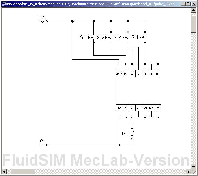
Think of a program, that can be realised in the logic block with the following properties: The lamp P1 should light up when the buttons S1 and S2 have been pressed simultaneously; thus, light up after pushbuttons S1 and S2 have been released again. The lamp should go out when pushbuttons S3 or S4 have been pressed.
Copy and validate your logic circuit in the lab-session!
A button can be pressed permanently by holding down the shift key while clicking.
Extend the circuit so that an electric motor is switched on and off in addition to the lamp. (Parallel connection!)
Task Logic-based control
Use FluidSim to solve the following tasks. Please choose one station, if you're done, choose the other station. Talk to your classmates, there is a limited number of stations
Conveyor belt
Workpieces are transported in every automated assembly. In the MecLab, a conveyor belt is provided for this purpose. The conveyor belt should not run continuously in order to save energy. Therefore, the conveyor belt should always switch on when a workpiece is placed at the start of the belt and stop when the transport task has been completed. The workpieces can be of any color.
How can it be achieved that the belt only runs when a workpiece is in contact?
Which logic component can be used to ensure that the motor runs as long as the workpiece is transported to the end of the conveyor?
Implement the belt functionality in FluidSim using a simulated motor and logic elements in the digital module.
Conveying and sorting tasks are important functions in any production. The task is to design a conveyor belt and an associated control program that has the following characteristics: Workpieces (black cans) are to be transported from the beginning of the belt to the end of the belt. The transport should start when a workpiece is placed at the beginning of the belt and stop after the workpiece has left the belt at the other end. Silver workpieces are to be sorted out onto the chute.
Expand the simulation of the conveyor belt which fulfills the described functionalities. Add an ON/OFF switch for the whole system. The functionality should be implemented using logic elements in the digital module.
Now, the system works in simulation mode. Thus, the next step is to test everything in real life.
Add a "Multipolverteiler" to your drawing. This element will make the connection from the real world MecLab station to the FluidSIM sketch! Connect the MecLab station to the PC via USB. Press play in FluidSim. If a Sensor is now triggered on the real machine, you will see the pins light up in FluidSIM. Check the pin assignment at the distributor ("Multipolverteiler").
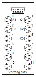
Assign the pins on the "Multipolverteiler" to the relays that control the actors in FluidSim. To do so, double click on the "Multipolverteiler" and assign the corresponding label.
Control the real conveyor belt via FluidSim.
What happens if you first place a silver can and shortly afterwards another silver can (distance approx. 3 cm) on the conveyor belt? Is it sorted out correctly?
Stack magazine
An important function of the stacking magazine station is the pressing of can and lid. A control system is to be designed for this purpose.
A vertically arranged pneumatic cylinder is to be used for pressing in, which is supplied with air by a solenoid valve and controlled by the control unit. The cylinder is to extend at the push of a button and remain extended as long as the button remains pressed. An important boundary condition is that, for safety reasons, the cylinder also returns to the upper end position in the event of a power failure.
Create a simulation of both cylinders in which the magnetic valves are controlled by buttons. The single-acting cylinder should be operated by one button, the double-acting cylinder by two buttons. (Verriegelung) Use flow control valves to adjust the operation speed.
Sensors are important components of any automated system. In the stacking magazine station, there is a magnetic limit switch which detects the position of the cylinder piston.
Now, a control system for the stacking magazine is to be developed with the following features:
-
The operator places a can in the assembly fixture and presses the start button.
-
The double-acting cylinder pushes a lid out of the magazine tower (onto the can) and then moves back to the starting position.
-
The single-acting cylinder presses the lid into the can for exactly 10 seconds.
-
The operator removes the finished workpiece (lid plus can).
-
The can and lid may be of any color.
Modify the circuit from the previous task so that the solenoid valves are controlled by the digital module instead of by pushbuttons. Add a start button and the magnetic limit switch of the double-acting cylinder and connect them to the inputs of the digital module.
Create the circuit for the plant in the digital module using logic elements. Test the control in the simulation. Add an ON/OFF switch for the whole system.
Add a "Multipolverteiler" to your drawing. This element will make the connection from the real world MecLab station to the FluidSIM sketch! Connect the MecLab station to the PC via USB. Press play in FluidSim. If a Sensor is now triggered on the real machine, you will see the pins light up in FluidSIM. Check the pin assignment at the distributor ("Multipolverteiler").
- Assign the pins on the "Multipolverteiler" to the relays that control the actors in FluidSim. - To do so, double click on the "Multipolverteiler" and assign the corresponding label.
Control the real stack magazine belt via FluidSim.
What happens, a) if you press the start button again during the pressing process? b) if you press the start button permanently?
Could this cause problems with the operation of the station? If so, extend your logic diagram to avoid this. Test again with the help of the simulation.