HandlingStation_E!Cokcpit
Table of Contents
Preparation: Handling Station
Goal
- To get to know and describe the structure and functionality of the handling station
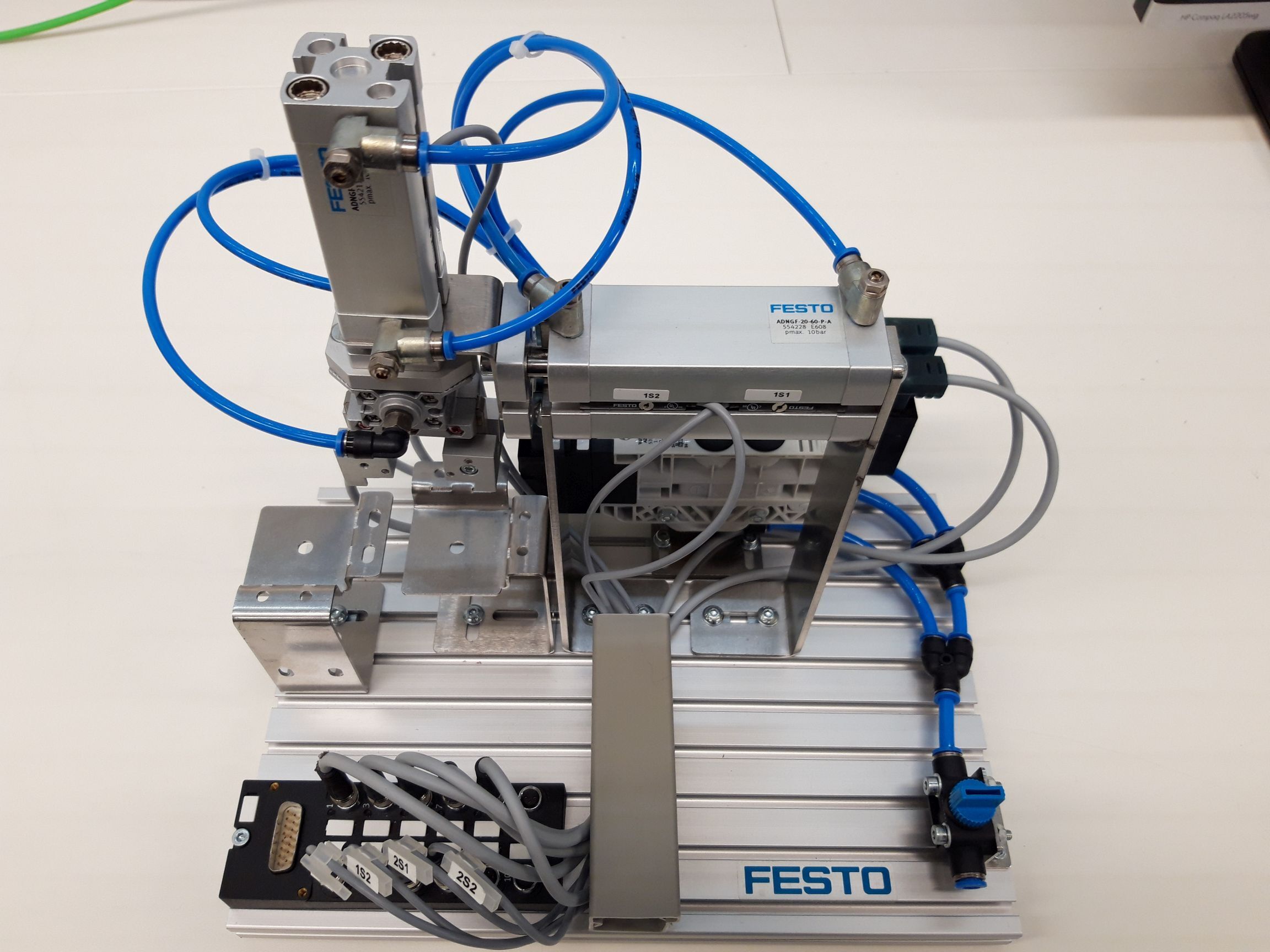
The station should mount a top part (which is on the right side) on top of a bottom part (which is on the left side). The station uses 2 different double acting cylinders and a pneumatic gripper.
The functionality of the station can be seen in this video: https://www.youtube.com/watch?v=Jav9SERe0sE
Handling Station Behaviour
- The resting position of the station is when the gripper is not engaged, the gripper is lifted and the transfering cylinder is pulled in!
- On command (by a tappler or other user input), the gripper should move down, close, move backup.
- Transfer the piece forward, move down, release.
- Then the station should return in its resting position.
In Software development, state machines are a tool that is very often used, to visualize and understand the behaviour of a machine, before developing the code of the controller.
Find a short intro into state machines here Unified Modeling Language (UML) state machines are used to model the behavior of a system or an object in terms of states and transitions. They are particularly useful in understanding and designing complex systems, especially in software and embedded systems.
States A state represents a condition or situation during the life of an object where it satisfies some condition, performs some activity, or waits for some event. For example, consider a traffic light:
- Green Light: The traffic light is green, allowing cars to go.
- Yellow Light: The traffic light is yellow, indicating that cars should prepare to stop.
- Red Light: The traffic light is red, stopping cars from going.
Each of these represents a different state of the traffic light.
Transition Conditions A transition is a change from one state to another. It occurs in response to an event and can have conditions that must be met for the transition to occur. These conditions are known as transition conditions or guards.
For example, in the traffic light scenario:
- The transition from Green Light to Yellow Light occurs after a certain period, say 60 seconds.
- The transition from Yellow Light to Red Light happens after 5 seconds.
- The transition from Red Light back to Green Light might occur after a pedestrian button press and a timer event.
These conditions ensure that transitions happen in a controlled and predictable manner.
Example Let's consider a simple state machine for a door that can be in three states: Closed, Open, and Locked.
- Closed State: The door is closed.
- Open State: The door is open.
- Locked State: The door is locked.
Transitions might be:
- From Closed to Open: When someone pushes the door handle.
- From Open to Closed: When the door is pushed shut.
- From Closed to Locked: When someone locks the door.
- From Locked to Closed: When someone unlocks the door.
In this case, the transitions depend on events like pushing the handle or locking the door.
By modeling these states and transitions, UML state machines help in understanding and designing the logical flow and behavior of systems.
Source: ChatGPT
Concept of Entry/Do/Exit: States in Detail
In UML state machines, each state can be divided into three parts: entry, do, and exit activities. These parts help to define what happens when the system enters, stays in, and exits a state.
-
Entry Activity: This action is executed when the system enters a state. It's like a setup phase. The entry activity is called once when the state is entered.
- Example: When a door enters the Locked state, the entry activity might involve engaging the lock mechanism.
-
Do Activity: This action is performed while the system remains in the state. The do activity is called continuously or repeatedly while the system is in the state.
- Example: While the door is in the Locked state, the do activity could be continuously monitoring the lock status to ensure it remains secure.
-
Exit Activity: This action is executed when the system exits a state. It's like a cleanup phase. The exit activity is called once when the state is exited.
- Example: When the door exits the Locked state (i.e., it is being unlocked), the exit activity might involve disengaging the lock mechanism.
Example with Entry, Do, and Exit Activities
Let's revisit the door example with these activities included:
-
Closed State:
- Entry: Ensure the door is fully shut.
- Do: Monitor for handle push.
- Exit: Prepare to open the door.
-
Open State:
- Entry: Move the door to the open position.
- Do: Keep the door open and monitor for someone pushing it shut.
- Exit: Prepare to close the door.
-
Locked State:
- Entry: Engage the lock mechanism.
- Do: Continuously ensure the lock remains engaged.
- Exit: Disengage the lock mechanism.
Summary
- Entry Activity: Called once upon entering the state.
- Do Activity: Called continuously while in the state.
- Exit Activity: Called once upon exiting the state.
These activities provide a clear structure for what should happen during different phases of a state's lifecycle, making the system's behavior more predictable and easier to manage.
Source: ChatGPT
Make yourself familiar with UML State Diagrams, e.g. here
Find accurate names for states of the handling station and draw a state machine diagram (using UML - unified modelling language - specifications). The state machine of the handling station should at least have 5 or 6 states. 2 of those states shoule be named "INIT" and "IDLE". Why are these states needed? What are the transition conditions to move from one state into the other? (also remember the sensors that are mounted onto your stations) Specify what should be done in the entry, do, and exit phases of each state!
Define the transition conditions between each state and the following state.
A drawn State Diagram is necessary to participate at this lab session!
Assignment: Handling Station
Whe you are programming, you may come accross text, which will be underlined in RED. This code may be wrong and needs revision!
Connect to PLC
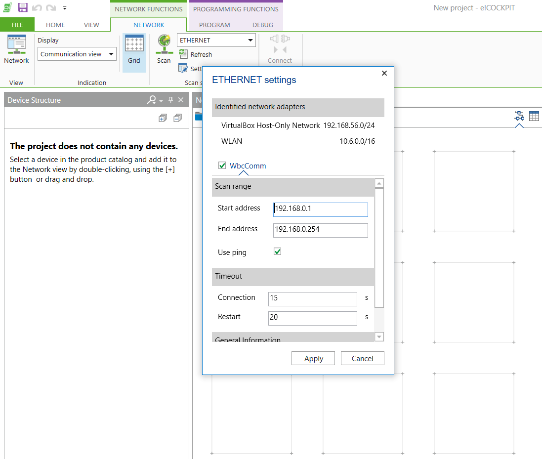
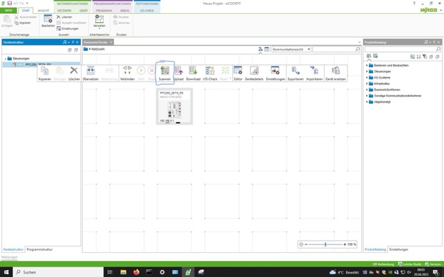
Scan for and connect to the PLC from inside e!Cockpit. This is how to do it: Take a look at the PLC rack and read the PLC's IP address. Navigate to Network - Settings and put in the right IP range to scan. For example, scanning in the range from 192.168.1.1 till 192.168.1.254 will detect all PLC's in this network that have IP addresses within that range.
📌 Please note that this scanning process can take multiple trials to detect the PLC. If a PLC is not detected immediately, scan again.
After detecting the PLC, click Apply All to add the PLC to your project
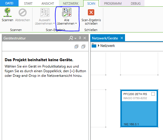
The IP address of the PLC used in this session is 192.168.0.1
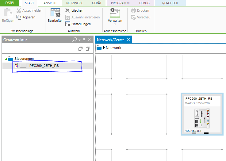
Note that now the PLC has been added to your project.
This has only added the PLC module itself. But the PLC has other modules attached to it that were not yet scanned for. Every module adds new functionality to the PLC. For example, module 750-430 is an 8-channel digital input card. Meaning that the wire-plugs on the 750-430 accept digital sensors like an inductive sensor, light beam sensor, etc.
If you are wondering what a certian module does, search its module number online.
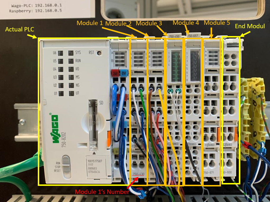
The PLC in this session has 5 modules inserted between the PLC and the End Module. Note that the End Module has to always be there at the end.
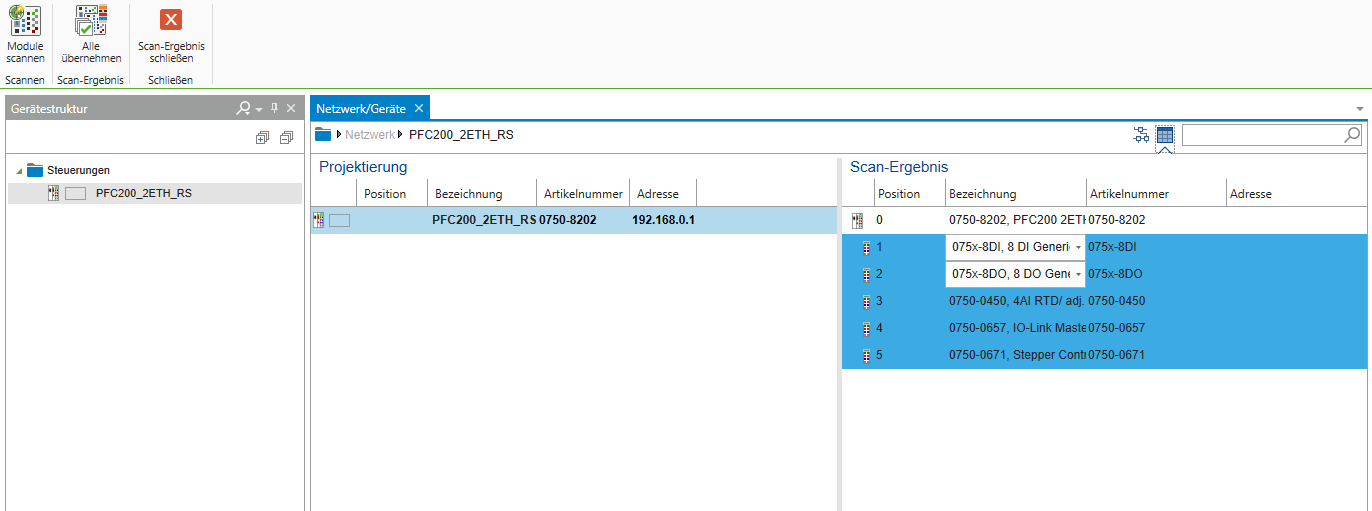
Right click on the newly added PLC and choose scan to scan for the modules inserted next to the PLC.
The scan results should identify 5 modules. Click add all to add all modules to the project
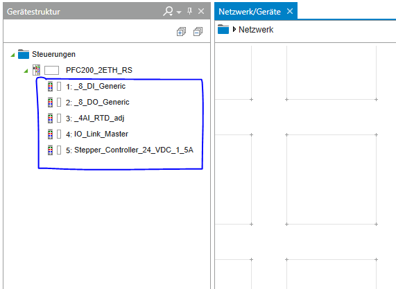
After adding all scanned modules, your device structure should look like this:
Connections to the PLC
State Machine as Enumeration
State machines can be implemented as enumerations in ST.
An enumeration is a user defined type that holds a specific number of elements. A variable of this datatype, can only have the values, defined in the enumeration.
In the case of state machines, each enumeration element represents a state.
To create an enumeration in e!Cockpit, navigate to Program Structure in the bottom left corner, right click on Applicaition and
select DUT.

Create an enumeration and give it the name STATES.
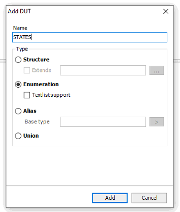
Add one state element for each state you have in your state machine. Separate each state by a comma and name each state according to your state machine diagram
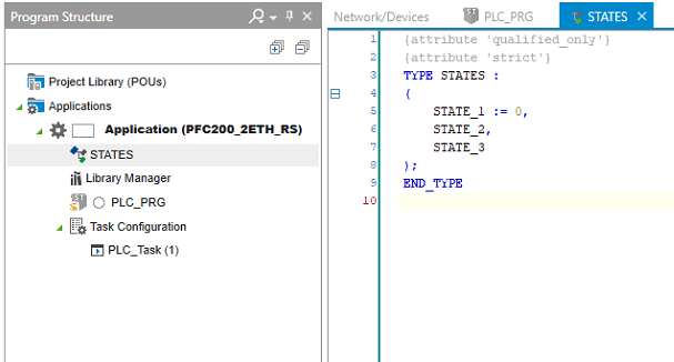
Example of an enumeration with unspecific state names. Note: you have to give states meaningful names (e.g., MOTOR_FORWARD, MOTOR_BACKWARD, etc.) not call the states STATE_1, STATE_2, etc.
PLC_PRG and the Switch Case Statement
change to the PLC_PRG. This is the main program that will be excecuted. Here you define variables and your code!
Create an instance of the STATES enumeration in you program (call it state) and an Entry boolean variable. Initialize your state variable with the INIT state.
tate : STATES := STATES.INIT; bEntry : BOOL := TRUE;
Signal Mapping
The PLC is wired to the conveyor belt's components as follows:
In the PLC_PRG create all necessary variables!
| Component | Input address | Output address |
|---|---|---|
| 1S1 | %IX1.0 | |
| 1S2 | %IX1.1 | |
| 2S1 | %IX1.2 | |
| 2S2 | %IX1.3 | |
| 1M1 | %QX0.0 | |
| 1M2 | %QX0.1 | |
| 2M1 | %QX0.2 | |
| 2M2 | %QX0.3 | |
| 3M1 | %QX0.4 |
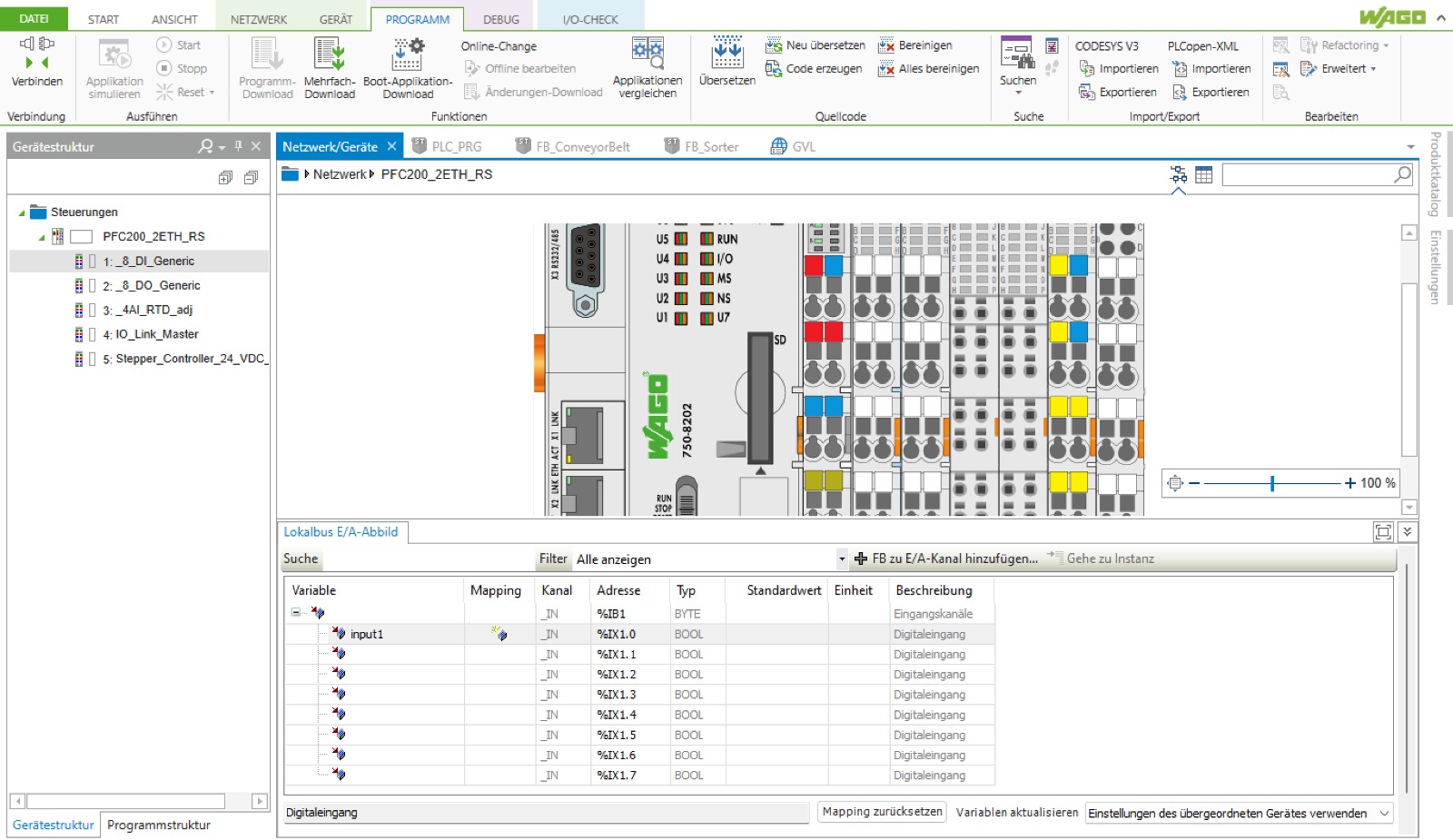
In this step you will connect programmed variables to hardware outputs. (Compareable to the labels in the Festo FluidSIM environment with the "Multipolverteiler")
Navigate to Device Structure and give these inputs/outputs suitable names to be used in the program. Double click on the field in the coloumn where "input1" is written. Type accurate variable names... (e.g._S1 for a optical sensor, check the table above!) You can double click on the fiel on the left, the click on the three dots, open Application - PLC_PRG and choose your variable!
variable names cannot start with numbers. To solve this problem name your variable with an underscore: _S1 or _1M1
Implementation
📌 Every state machine should include the INIT state. This is the first state the program should run when powered. If you didn't include an INIT state in your preparation, include one now.
PROGRAM PLC_PRG
VAR
    state : STATES := STATES.INIT;
    Entry : BOOL := TRUE;
END_VAR
In the program code window, write a CASE OF statement to switch between your states. Use the Entry variable to implement the entry code.
CASE state OF

    //-----------------STATES.INIT-----------------------------------------

    STATES.INIT:
        IF bEntry THEN
            bEntry := FALSE;
            // insert "entry" code here. This code will be carried out only once upon entry to the state.

        END_IF
        // insert "do" code here. This code will be carried out every PLC cycle while the program is in this state.

        //exit
        IF <exit_condition_here> THEN
            bEntry := TRUE;
            state := STATES.<next_state_here>;
            // insert "exit" code here. This code will run only once upon exiting this state.

        END_IF

    //-----------------<next_state>-----------------------------------------

    STATES.<next_state_here>: // repeat the pattern above for every state.
        .
        .
        .
        .
        .
END_CASE
Program your drawn state machine!
With the double acting cylinders, do not set both outlets as TRUE at the same time. Whenever you set an outlet as TRUE, be sure to follow it with the reverse on the opposite outlet.
// retracts cylinder 1
b1M1 := FALSE;
b1M2 := NOT b1M1; // this makes sure that not both outlets are actuated

// extends cylinder 2
b2M1 := TRUE;
b2M2 := NOT b2M1;
Timer / Delay
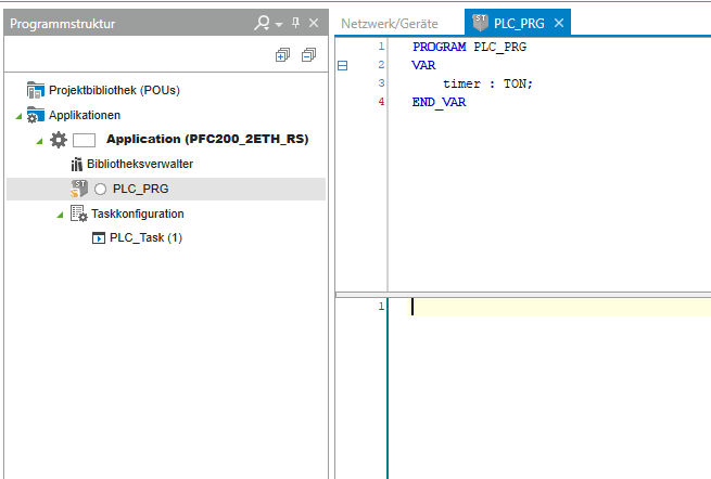
To use a timer, create a timer variable in PLC_PRG and call it anything, for example, timer. This variable is of data type TON. Give it no default value. TON Documentation
Your timer declaration may look like this:
When attempting to use the timer in the main program, you may see the following TON documentation.
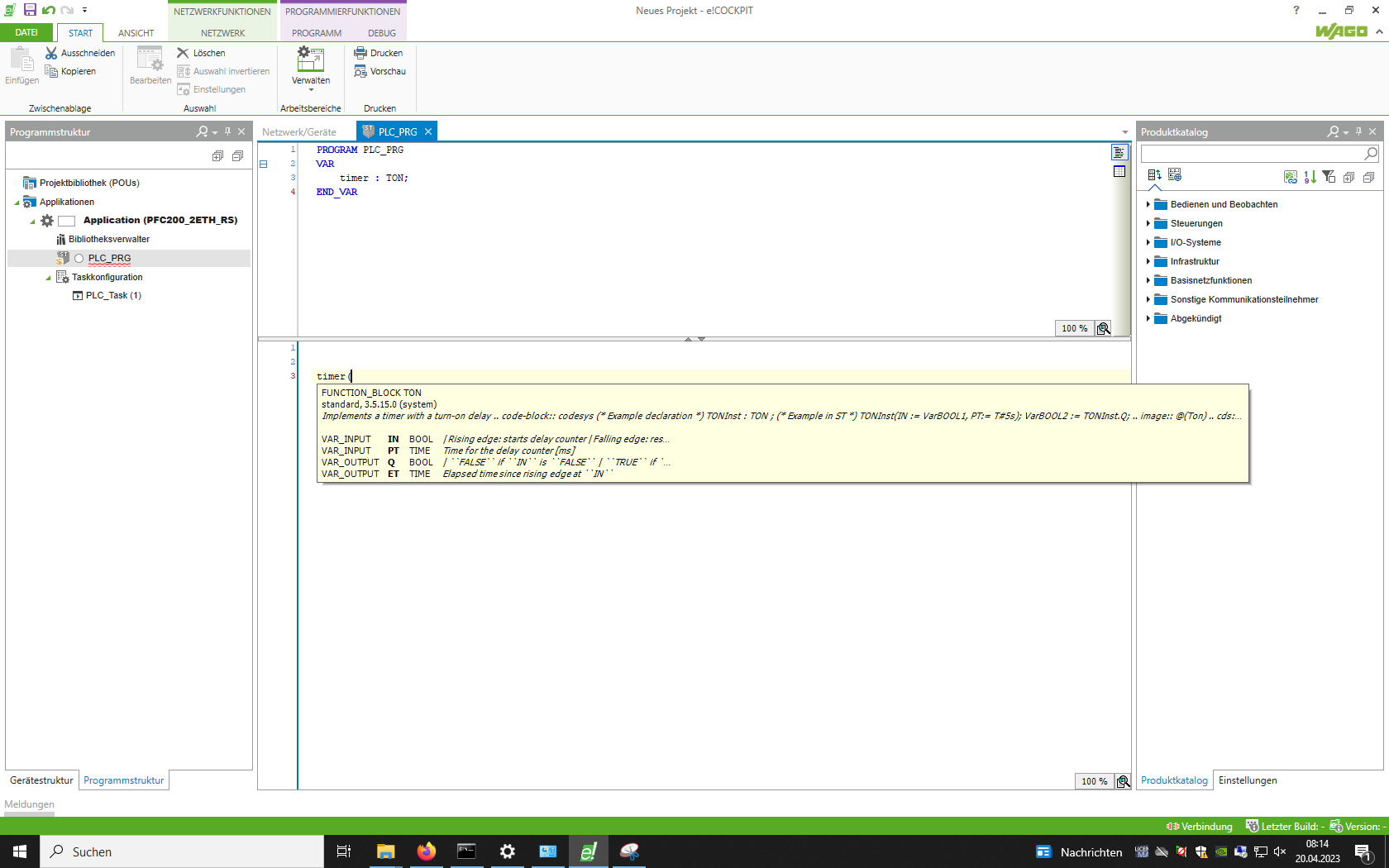
This timer function block (of type TON) accepts 2 inputs, namely IN and PT, and gives us 2 optional outputs, namely Q and ET.
IN sets the timer, PT gives the time value that the timer should count , Q is set to TRUE when the timer finishes counting , ET gives the elapsed time since IN was set to TRUE
To check if the timer has counted untill the end, check if timer.Q is TRUE. Do not forget to reset IN after the counter has finished counting, otherwise
the counter wont be usable again.
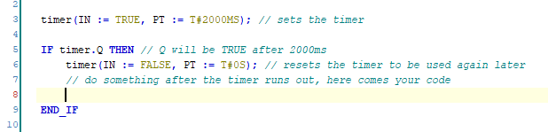
timer(IN := TRUE, PT := T#2000MS) calls the timer functionblock every cycle. This needs to be done to excecute the timer.
Upload the code
After writing the program, connect the PLC to the station using the 15-pin plug attached to the PLC rack. Upload the program to the PLC and test if it works as intented.
To upload the code to the PLC, select PROGRAM and CONNECT in the top menu bar.
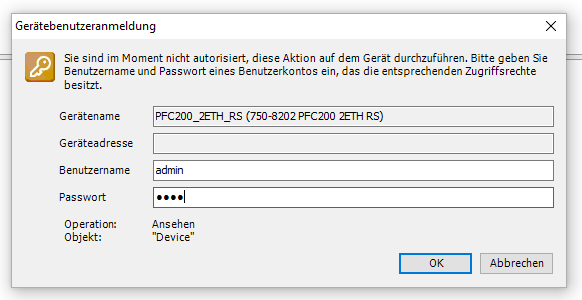
If you are asked for credentials, consider these: Username: admin, Password: wago
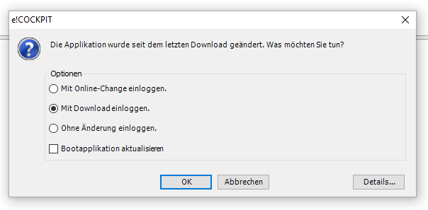
If you are asked for the options on how to download your program to the PLC, please select ``login with download```
Be sure to start your program with the start button in the top menu-bar!