FluidSimRelayTech
Table of Contents
Lab Session 1 - Relay Technology:
📌 What's the goal of this lab session?
In this lab session, you will be introduced to the fundamentals of control engineering. Topics will include basic concepts in electronics and pneumatics. While relay-based logic is considered an older technology, it remains a valuable foundation for understanding control systems and developing logical thinking skills.
Relay technology represents an early form of electrical control, relying on electromechanical switches to manage circuits. In a relay, an energized coil generates a magnetic field, causing a metal armature to move and either open or close electrical contacts. This basic mechanism allows relays to control the flow of electricity in a circuit.
Relays were essential in early control systems, enabling simple logical operations such as AND and OR functions. By arranging relays in specific configurations, engineers could create circuits that responded to various inputs with specific outputs, akin to the basic operations performed by modern digital logic gates.
Despite their limitations, relays laid the foundation for more sophisticated control technologies. Their ability to perform basic logical operations helped pave the way for the development of digital logic circuits using semiconductor components like transistors.
In summary, relay technology played a crucial role in early electrical control systems, providing a means to perform basic logical operations. While relays have been largely replaced by more advanced technologies, their legacy continues to influence modern digital control systems.
(Source: ChatGPT)
Preparation
Festo Programming Stations
The following sections are required to understand the station functionalities.
An overview of the stations is provided in this video: https://www.youtube.com/watch?v=Jav9SERe0sE
Conveyor belt

Assign the correct designation to the components and describe their task in the station.

Create a principle schematic sketch of the conveyor belt. Which components are controllable? Which actuators and which sensors are used?
Stack magazine
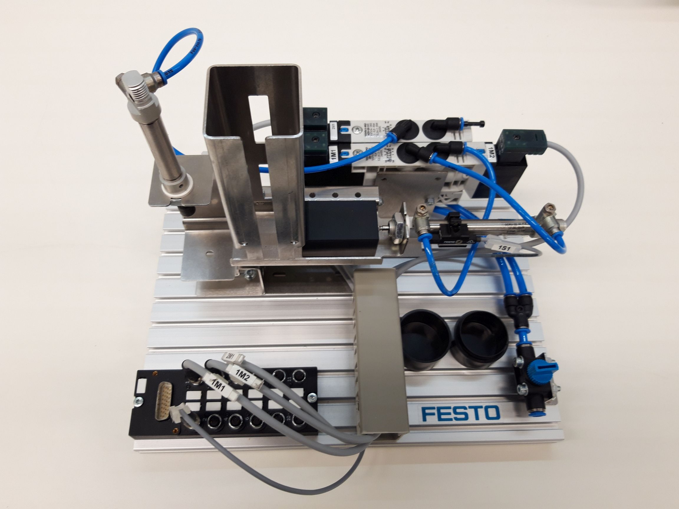
Assign the correct designation to the components and describe their task in the station.

Create a principle schematic sketch of the stack magazine. Which components are controllable? Which actuators and which sensors are used?
An important function of the stacking magazine station is the pressing of base and lid. A control system is to be designed for this purpose. A vertically arranged pneumatic cylinder is to be used for pressing in, which is supplied with air by a solenoid valve and controlled by the control unit. The cylinder is to extend at the push of a button and remain extended as long as the button remains pressed. An important boundary condition is that, for safety reasons, the cylinder also returns to the upper end position in the event of a power failure.
Which type of cylinder would you use for the described pressing process (single or double acting cylinder) and why?
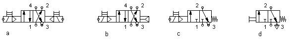
Which one of the following valves would you use?
Design a pneumatic circuit diagram from the selected components. If you have an instance of FluidSIM®, test the function in the simulation.
Do not forget the compressed air source and a manual push button to start the cylinder.
Test the circuit in simulation mode by clicking on the manual override of the valve with the mouse.
Handling station
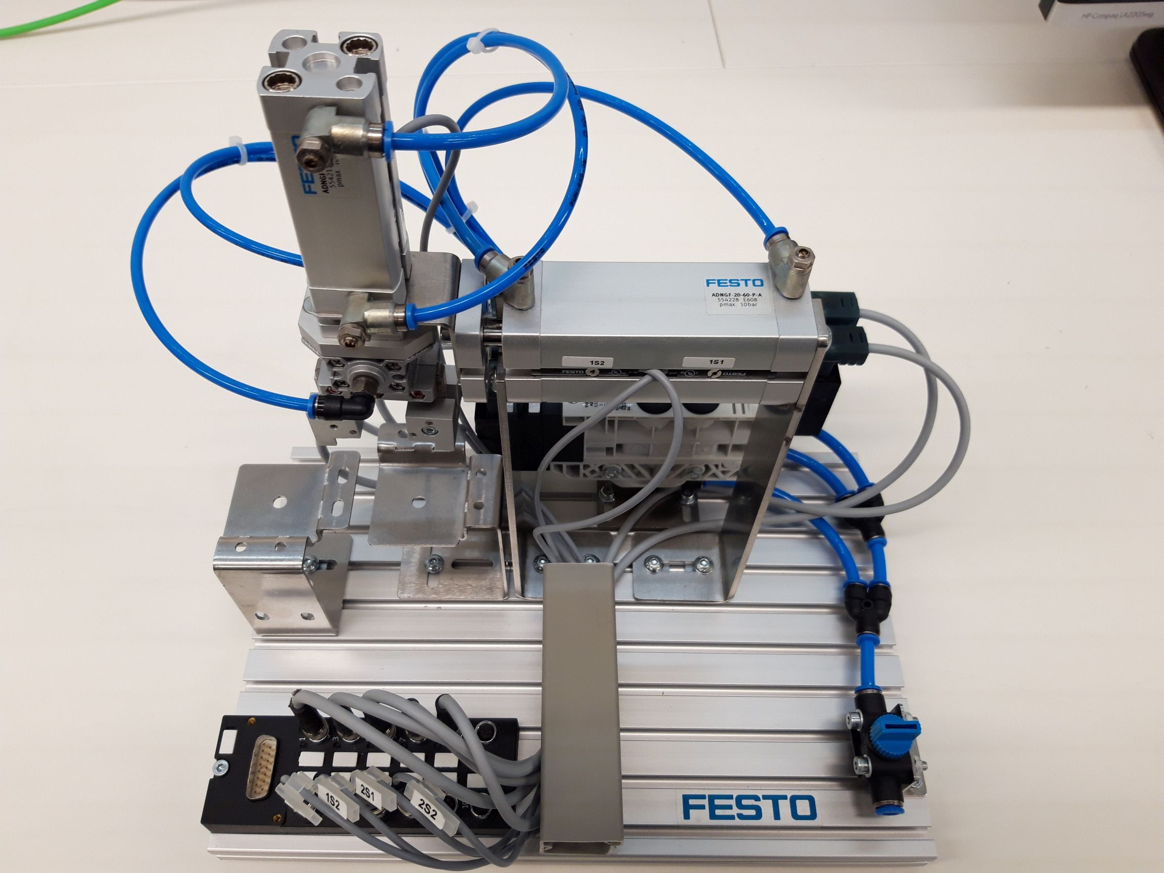
Assign the correct designation to the components and describe their task in the station.
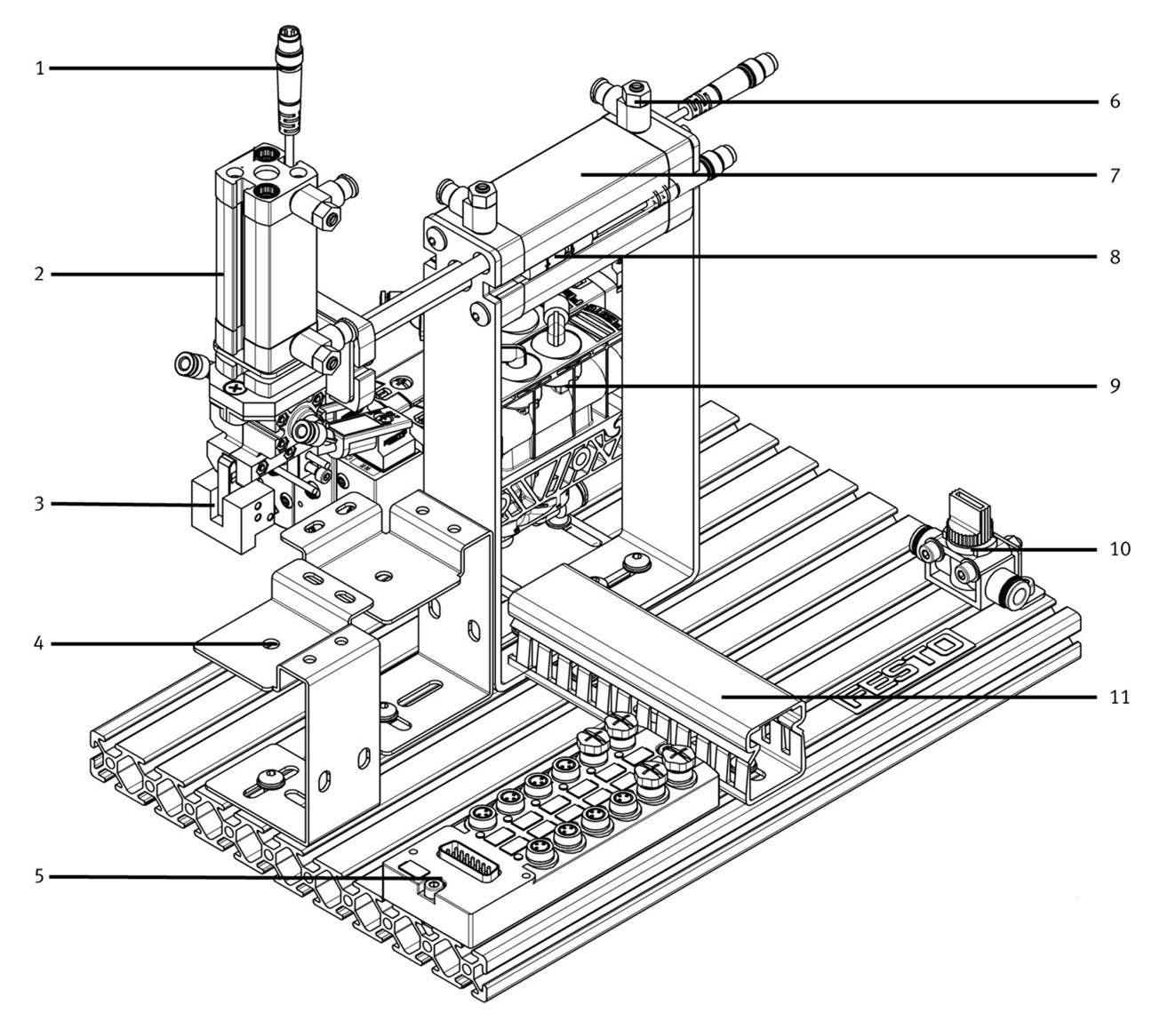
Create a principle schematic sketch of the handling station. Which components are controllable? Which actuators and which sensors are used?
The handling station is a classic example for a pick and place performance that is used very often in automation technology. (in german: Umsetzer) The resting state of this station should be when cylinder 7 and cylinder 2 are retracted. When started, the station moves down, grabs the can, moves up and forward, down and the places it back.
Design a pneumatic circuit diagram from the selected components. If you have an instance of FluidSIM®, test the function in the simulation.
Do not forget the compressed air source and a manual push button to start the cylinder.
Test the circuit in simulation mode by clicking on the manual override of the valve with the mouse.
Electronics Intro
The following section contains an introduction to the basic electronic parts, which are used during the practical sessions. Please carefully execute the todos, as this knowledge is required for the practical session.
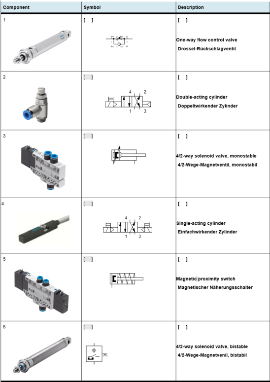
Assign the correct symbols and descriptions to the following components. Feel free to download the image and add the text with your tablets if you have any. If not, make a list on paper and fill the table with the corresponding number and information.
Pos. 4 is a Sensor!
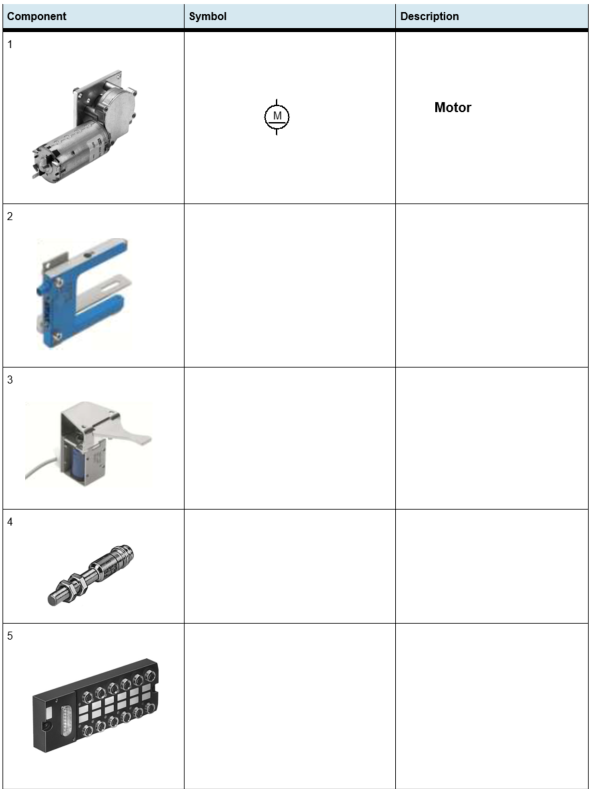
Assign the correct symbols and descriptions to the following components.
DC-Motor
The DC motor is one of the most important drives of all. It is used in many consumer electronics devices, household appliances, toys, and industrial machines. In this task, a control for this type of motor is to be developed.
Find out how the DC motor and the solenoid work and answer the following questions:
a) What must be done to change the direction of the motor? (the motor is controlled via 2 relays) b) Can the direction of the solenoid be changed?
Program logic can be created by using relays in different designs.
Look up and sketch the symbols for pushbuttons (Taster), switches (Schalter), make contacts (Schließer), break contacts (Öffner), and changeover contacts (Wechsler). What are these components used for?
Relays have a primary and a secondary side. The rectangular block represents the primary coil. If current is flowing through this block, the relay has the possibility to trigger a certain element. These elements in the "relay" category can be closing, opening, .... switches.
To connect the primary and the secondary side of the relay, double click the rectangular relay block. Here you can add a Label (German: "Marke"), e.g. "K1". Double click the secondary side (closing switch - Schließer) and add the same label name. Those two elements are now connected "invisibly"
In the image below: All the elements labeled with "K1" are now connected. Once a current can flow through the relay of K1, the switches on the left and on the right (above the lightsource) will close!
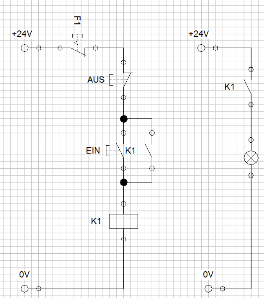
Why are two voltage circuits depicted here?
Think of a circuit in FluidSIM® with which the DC motor can be switched on and off manually, and the running direction can be changed.
Do you need two voltage circuits? (What voltage levels do large motors usually have?) How can you "connect" the relays and to switches in FluidSIM?
In the lab session, test and validate your circuit.
Extend the previously created circuit so that the DC motor is indirectly switched on and off and reversed via relays. (Use a control and a power-circuit!)
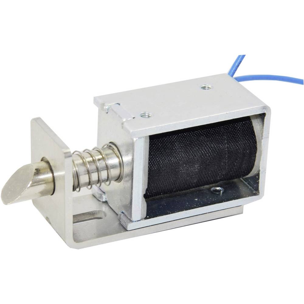
Solenoids
Solenoids provide an electric alternative to pneumatic cylinders. They can operate fast and are controlled easily.
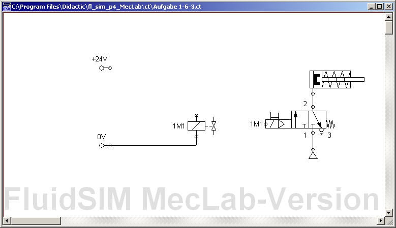
Think of a control for a solenoid coil with a pushbutton and a relay in FluidSIM®. To do this, complete the circuit diagram shown below. (The solenoid is represented by the pneumatic circuit.)
In the lab session, test and validate your circuit.
For safety reasons, a two-hand control (German: Zweihandbetrieb) is often used. In this case, a machine may only start when two buttons are pressed. This is to prevent the machine operator from reaching into the machine with one hand while it is operating.
Think of a circuit for two-hand control of a single-acting cylinder.
In the lab session, draw and validate the circuit in the simulation mode of FluidSIM®. Could this function also be implemented with switches?
Check your options in FluidSim to create time-based actions (e.g., wait for 10s till returning the cylinder again).
Pneumatics Intro
The following sections contain an introduction to pneumatic elements and their usages. Please carefully execute the todos as this knowledge is required for the practical session.
Match the images, sketches, and descriptions accordingly.
Create basic sketches with an air source, a single-acting cylinder, and one valve. The valve should control the cylinder.
What do you have to change if you want to use a double-acting cylinder?
Task: Relais-based control
This task shall be handled during the lab session. Please read through this section before the lab session.
Use FluidSim to solve the following tasks. Please choose one station, if you're done, choose the other station. Talk to your classmates, there is a limited number of stations
Conveyor belt
Workpieces are transported in every automated assembly. In the MecLab, a conveyor belt is provided for this purpose. The conveyor belt should not run continuously in order to save energy. Therefore, the conveyor belt should switch on, when a workpiece is placed at the start of the belt and stop when the transport task has been completed. The workpieces can be of any color. Use the sketch from the preparation as a guide.
Create a circuit in FluidSIM® in which the optical and inductive sensors activate a lamp when they switch. Simulate different switching states. Test different objects (e.g., plastics, metal, coins, hand, paper) and write down the sensors' behaviours.
How can it be achieved that the belt runs only when a workpiece is loaded on the belt?
Implement the belt functionality in FluidSim using a simulated motor.
Conveying and sorting tasks are important functions in any production. The task is to design a conveyor belt and an associated control program that has the following characteristics: Workpieces (black cans) are to be transported from the beginning of the belt to the end of the belt. The transport should start when a workpiece is placed at the beginning of the belt and stop after the workpiece has left the belt at the other end. Silver workpieces are to be sorted out onto the chute.
Expand the simulation of the conveyor belt which fulfills the described functionalities. Add an ON/OFF switch for the whole system.
Now, the system works in simulation mode. Thus, the next step is to test everything on the provided hardware.
Add a "Multipolverteiler" to your drawing. This element will make the connection from the real world MecLab station to the FluidSIM sketch! Connect the MecLab station to the PC via USB. Press play in FluidSim. If a Sensor is now triggered on the real machine, you will see the pins light up in FluidSIM. Check the pin assignment at the distributor ("Multipolverteiler").

Assign the pins on the "Multipolverteiler" to the relays that control the actors in FluidSim. To do so, double click on the "Multipolverteiler" and assign the corresponding label.
Control the real conveyor belt via FluidSim.
Stack magazine
An important function of the stacking magazine station is the pressing of can and lid. A control system is to be designed for this purpose.
A vertically arranged pneumatic cylinder is used for pressing in.
Create a simulation of the single-acting cylinder which operates the pressing activity when a virtual button is pressed.
The function of the stacking magazine is to store workpieces and eject them individually. The parts are pushed out by a double-acting pneumatic cylinder. A control system should now be developed for this.
Create a simulation of the pusher which ejects the parts. Use one valve and two flow control valves in addition to the cylinder. After pressing a pushbutton (in the software), the double-acting cylinder extends and moves the workpiece to the pressing position. After pressing another button, the pusher retracts again.
The flow control valves should be used to adjust the operation speed.
Sensors are important components of any automated system. In the stacking magazine station, there is a magnetic limit switch which detects the position of the cylinder piston.
How can you ensure that the single-acting cylinder does not extend until the double-acting cylinder is fully extended? Which (logic)component is required?
Create a new circuit to simulate the whole functionality of the stack magazine. Add an ON/OFF switch for the whole system.
Add a "Multipolverteiler" to your drawing. This element will make the connection from the real world MecLab station to the FluidSIM sketch! Connect the MecLab station to the PC via USB. Press play in FluidSim. If a Sensor is now triggered on the real machine, you will see the pins light up in FluidSIM. Check the pin assignment at the distributor ("Multipolverteiler").
Assign the pins on the "Multipolverteiler" to the relays that control the actors in FluidSim. To do so, double click on the "Multipolverteiler" and assign the corresponding label.
Control the real stack magazine belt via FluidSim.
Problem Solving
Will be expanded if required.